

Description
Overview
For this assignment, I’d like you to make two 2-D drawings, one 3-D scene, and a simple animation, all using the opengl.js library we used in Project 1. You will modify scene.js, the code provided at a link on this page, so that it displays each of these four scenes. The scenes should consist of shapes you create using GL_TRIANGLE vertex layout requests. The shapes should be placed in the scene by applying transformations to the coordinate frame using glScalef, glTranslatef, glRotatef. These scenes will typically be hierarchical, so you will want to issue glMatrixPush and glMatrixPop commands to save and restore coordinate frames as you lay them out.
Download
Here is the starter code for this assignment.
The Assignment
Modify (or completely rewrite) scene.js so that it generates each of these scenes:
- A 2-D drawing using the transformation stack, like my house scene.
- A 2-D drawing of a recursive figure generated like my Sierpinski carpet.
- A 3-D still life that places objects on a table, some from Project 1.
- A cycling animation of an articulated figure, like my waving arm.
Make it so that the program user can select which scene is displayed by pressing a button on the page. You can also add controls so that the user can play with each scene.
A 2-D drawing
The first thing you must make is a 2-D drawing of your design. That drawing can be of anything, except it must be in the spirit of my house drawing, and have similar complexity (or more). That house drawing uses only a few graphics primitives—a “unit” right triangle, a unit disk, a unit square, and a 1×2 rectangle—but scales, rotates, and translates the coordinate system so that, when these figures are drawn, they get placed all over the screen to form the drawing.
The whole point of you completing this task is for you to get practice using the OpenGL transformation stack by making glPushMatrix, glRotate, glScale, glTranslate, and glPopMatrix calls.
To do this, you will replace the call to drawHouse within the function draw in scene.js so that it calls a function that draws your 2-D scene. The coordinate frame set up by draw is a 5.0 unit wide by 4.0 unit tall rectangle with the origin sitting in the center of the scene. This means that the xx coordinates should live in the range [−5/2,5/2] and the yy coordinates live in the range [−2,2]. You can layer the drawing so that some elements get drawn above or behind other elements. The range of zz coordinates you can use for this layering should also lie between −2 and 2. Negative zz coordinates sit further away than positive ones, so the positive zz axis is pointed out of the screen.
A recursive drawing.
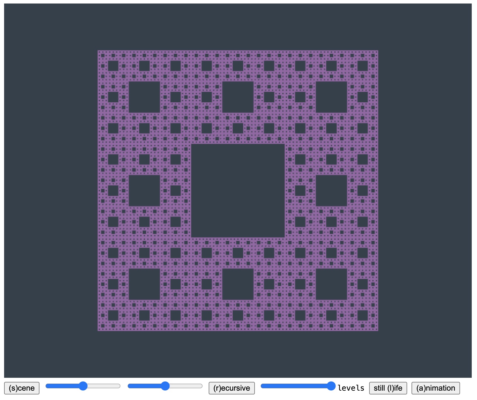
I described my procedure that draws a Sierpinski carpet in class. This is the purple square depicted by the starting code when you select (r)ecursive. I’d like you to generate a similar recursive fractal figure with a procedure. You have several options:
- A Sierpinski triangle. This is similar to the Sierpinski carpet, but renders as a triangle.
- A Koch snowflake.
- A recursive figure of a branched leaf, or something similar.
I describe each of these options just below.
To do this work, you’ll want to replace the call to drawSquareSierpinski within the code for draw in scene.js. The coordinate frame used by draw for the recursive figure is the same as the one used for the house scene, but there is a call to glScalef(3.0,3.0,3.0) just before the call to drawSquareSierpinski. The Sierpinski square code draws its recusrive figure with coordinates within ±1/2, but that scale call makes it a 3×3 unit figure within that 5×4 unit region.
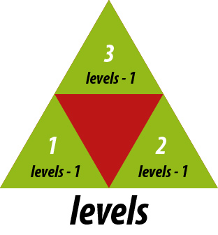
. Sierpinski triangle. For this figure, you’ll want to write a recursive function that produces it, parameterized by a levels parameter. This parameter will be used to drive the recursion. When levels == 0 you just draw the base geometric shape of the figure (an equilateral triangle). When levels > 0 you’ll instead recursively call this function several times. My carpet code calls drawSquarepinski 8 times. For the triangle yours would call its own procedure 3 times. Each call is made after a scaling and translation of the coordinate frame. For example, for the triangle figure you’ll scale the frame by 1/2rd, then call the function with no translation, then with a unit translation along the one side, and then a unit translation along the other side. You’ll need glPushMatrix and glPopMatrix to enter, then back out of the (transformations made by these) recursive calls. Note that each of these recursive calls should be made with the parameter levels - 1.
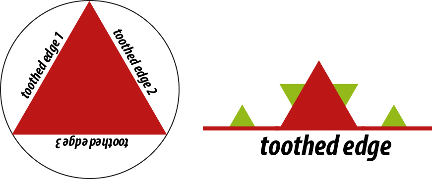
. Koch snowflake. After an initial triangle is drawn, you’ll want to draw the three “toothed” sides of the triangle. You’ll do this with a function def KochSide(levels). This function acts similarly to the drawSquarepinski function of the starter code. It should act recursively. For levels > 0, you’ll make four recursive calls to KochSide(levels - 1), to lay out the four smaller toothed edges that form the toothed edge at this level. These are shown below as the green triangles.
For levels == 0 you just draw a single triangular tooth, centered on the edge. Note that at the highest level, you’ll be calling KochSide three times, at three different locations and orientations, to make the three sides of the snowflake. Done right, because of the tooth layout, the three sides around the top-level triangle will appear as a 6-pointed snow flake.
. Branched leafing. This figure is generated similarly as the other two just described, but has more flexibility in how it can be designed. This Wiki entry and this page explain figures similar to what I’m requesting.
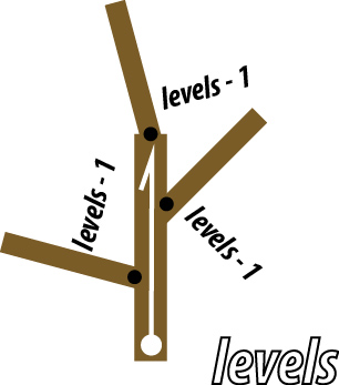
The branched leafing figure procedure is also parameterized by levels and is depicted below. In its layout, we think of it as having a “spine” of a vector ray, of a certain length, emanating from some branch point. This spine gives the overall scale and direction of the figure. The figure itself is self-similar: part way up the spine are three branch points. One at the tip of the ray, and one on each side of the ray. Emanating from these three branch points is a figure, just like the one we are describing, shooting off in three directions, each at an angle off the spine, and each at a smaller scale.
To draw this, you draw the spine ray as a thin brown rectangle. You then draw two shoots off the spine for the other two branches, also as thin brown rectangles. You then recursively draw the figure with levels - 1 emanating from these branch points at their reduced scale. At the base case levels == 0 you draw, say, a green leaf instead of the branched spine.
You can make it so that the user to controls the shape of the “frond” produced, say, by allowing them to control the angle of the shoots, etc. I’ve added two sliders to the demo that control the angle of the branches in the main scene for the house. You could instead have these control your branched figure.
A trickier means to control the shape would be to have the user drag the figure. You can take a look at my handling of the mouse clicks and drags that place the sun in the main scene of the house.
Still life
If you click on the still (l)ife button within the starter application, the display will switch to a depiction of an empty cubical room, one that is reminiscent of a Cornell Box. It has a red wall on the left, a blue wall on the right, and the back wall, the floor, and the ceiling are white. For this part of the assignnment you are to stage the room so that it has a table with a few 3-D objects from Program 1 sitting on it. The image below shows a possible solution for this.
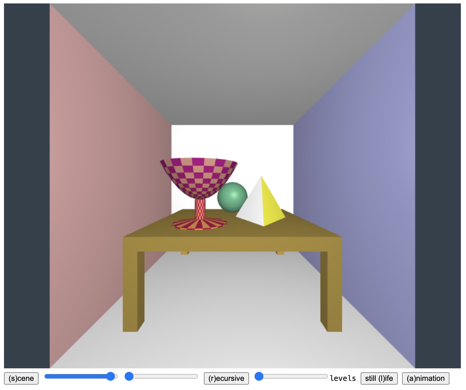
You’ll want to add your code to the function drawStillLife which already contains a call drawRoom that draws the room. Within that code, the origin is centered in the middle of the room. And the room has coordinates ranging within −1.0 and 1.0. The room’s dimensions are thus 2 × 2 × 2. Any object you place in the room that has parts that sit closer than +2.0 will be trimmed away by the graphics system.
The table that you invent must be made of repeated calls to glBeginEnd("Cube"), but with glScalef and glTranslatef calls elongating or flattening the cube to make the table elements. The table should be square with a top that is 1.5 units wide and deep. The table legs and the table top should be 0.1 units thick. The table should be 0.65 units high.
Place at least three objects on top of the table: one should be a sphere, one should be your platonic solid from Program 1, and one should be one of your surfaces of revolution from Program 1.
I’ve added two features of the application to help you debug your still life creation. If you click on the still (l)ife button while viewing the still life, a swinging light bulb will appear and illuminate the scene. This will give you a better sense of the three dimensional qualities of your layout. Also, if you press the v key, the view will switch from a perspective view to an orthographic one. You can use this other mode to see whether your objects are properly placed on the surface on the table.
Animation
I shared a demo that draws a 3-D wireframe diagram of an arm with a hand and fingers. This articulated figure changes the angles of several joints over time (the shoulder, the elbow, the wrist), with one incremental change per frame of the animation that runs at roughly 60x a second.
Make your own animation of a jointed figure made up of rigid components, whatever you like, and have its positions and angles change over time. It could be something like Pixar’s Luxo Jr. jumping around in a circle, a simple animal running, whatever you like. It should have at least three rigid components at angles, and move in some way, both its angle and its position.
This does not have to be phenomenal or too detailed. Just, like the arm code, get some practice drawing a limbed or jointed figure and use the transformation stack to place it and to wiggle it.
You write this code by replacing the call to drawWavingArm with a call to your function. My code uses three global variables gShoulder, gElbow, and gWrist that control the animation of the waving arm. These update every time a frame of the animation is rendered. You will want to invent your own global state for your animation similarly.
Handing In
Just as in Project 1, use Gradescope to submit the individual files that make up your working program. Submit every file that’s needed. That way I can download it from Gradescope (it gets packaged as a folder) and run it in my browser. Should you want to included happy accidents or bloopers you can also include, say, a ZIPped folder of snapshots that you want to share of your pretty mistakes.
Please hand in what you have completed by the deadline, even if you haven’t completed everything or the code isn’t working. You can always submit revisions later for some possible credit.
Report
Include a text file named submitted.md, or submitted.txt, that tells me, briefly, everything you completed for the assignment, and some of the choices you made. Document your code, as well. The documentation should be richer if there was some non-standard or particularly tricky technical problem you had to solve. Your notes on this will help me evaluate the work. Cite any sources you rely upon. Also, let me know about any bugs you have, or what does/doesn’t work.
Goals and Bonuses
For all parts of this assignment I am open to you taking some liberty in what you produce, just so long as you are mimicking the techniques I’m suggesting. The key thing I want is for you to work by transforming the coordinate system while pushing and popping the transformation stack, and thus for you to generate scenes that have a hierarchical specification.