

Description
Overview
This assignment has you invent several geometric models of surfaces so that they can be displayed in a WebGL application. We model surfaces as collections of triangular facets that sit in 3-space. Each of the three corners of each facet are specified by an (x,y,z) coordinate, and the coloring of the facets are given as (red, green, blue) triples. Having describing all the vertices and facets of the surface, and its material properties, the surface description is then sent to the graphics hardware to be displayed on a WebGL canvas embedded in a web page.
The starting code for this assignment can be downloaded here. It includes a web page showcase.html that relies on the Javascript file showcase.js and a few other supporting files. When that web page is loaded into the browser, it can already display one of three objects:
- A faceted model of a tetrahedron (press
1). - A faceted model of a cube (press
2). - A faceted model of a cylinder (press
3).
These models are generated and displayed by these functions:
- Three
makeObject functions, each usingglBeginandglEnd, that describe the objects. - A
drawObject function that usesglBeginEndto show each object using WebGL.
The actual names are makeTetrahedron, makeCube, and makeCylinder. We describe this code in more detail below. You will extend the code to describe a few more models and render them as additions to the object showcase app.
Downloads and Links
The assignment
You are to add these models to the object showcase app:
- Sphere: A faceted model of the surface of a sphere.
- Platonic: A faceted model of one of the three other Platonic solids.
- Torus: A faceted model of the surface of a torus.
- Revolution: Two other surfaces of revolution.
Make the application so that these can be selected and shown by the user using both the keyboard and by clicking a designated button below the viewer.
The models you are assigned are each described more carefully below just after we describe how the existing shapes are handled by the code you have been given.
Starter code
Rather than directly work with the WebGL library, you will instead work with functions defined in opengl.js. The showcase app only calls functions from this library to do its WebGL work. This library was hand-built for CSCI 385 and is designed to mimic the kind of CG coding done using OpenGL libraries. You will find it a little more intuitive to work with, closer to how you might think about procedurally drawing shapes in 3-D. We’ll use this library throughout the semester and gradually learn the underlying WebGL work that it performs.
There are five important functions that you will use from the library. Four of them are used for describing a surface that you want your application to display. The fifth one is invoked when you want a previously-described surface to actually be displayed.
Object description
Here are the four OpenGL library calls used for surface description. You might scan this section quickly then look at the example of their use just below:
• glBegin(type, name, varying)
This starts the recording of a description of a geometric object of the given name (a string). For this assignment, type should be GL_TRIANGLES, meaning that the surface will be described as a bunch of triangles sitting in 3-space. If varying is true then the colors of each facet can vary and that variation will be recorded. If varying is false then only the vertices are recorded. The color of the object should be set later when the object is drawn.
• glVertex3f(x, y, z)
This describes one of the vertex corners of the object being recorded. When describing a GL_TRIANGLES object, these calls are normally made in groups of three, a total of nine coordinate values for each triangular facet.
• glColor3f(red, green, blue)
This call sets the color to be used for subsequently described components of the object currently being recorded. The values of red, green, blue, should be between 0.0 and 1.0. They give the additive color components, that is, using the typical web RGB color space. If varying was set to false for glBegin, then you normally set the color of the object before describing each of its vertex locations. If instead varying is set to true, then typically you set this before each triplet of glVertex3f calls that describe a triangle. You use this to set the color of that triangle. If you instead change colors in the middle of describing the facet, then the triangle will be shaded with a blending of the different colors of its vertices.
• glEnd()
Stop recording the description of a geometric object. There should be one glEnd for every glBegin, and their use should not be nested. This means that, from the perspective of the OpenGL library, the calls you make should be glBegin, some more description, glEnd, glBegin, some more description, glEnd, etc. There shouldn’t be two calls to glBegin without an intervening glEnd.
Example: recording a colorful triangle
The code below could be used within showcase.js to describe a three-color triangle similar to the one displayed by the triangle WebGL demo:
function makeTriangle() {
    glBegin(GL_TRIANGLES,"Triangle",true);
    glColor3f(1.0, 0.0, 0.0)                    // pure red
    glVertex3f(-0.5, -Math.sqrt(3.0)/6.0, 0.0); // left
    glColor3f(0.0, 1.0, 0.0)                    // pure green
    glVertex3f( 0.5, -Math.sqrt(3.0)/6.0, 0.0); // right
    glColor3f(0.0, 0.0, 1.0)                    // pure blue
    glVertex3f( 0.0, -Math.sqrt(3.0)/3.0, 0.0); // top
    glEnd();
}
What you see above is the placement of three vertices in 3-space, but they are really just sitting in the x,y-plane forming an equilateral triangle, as shown with the coordinates below:
(1/2,s)bluered(-1/2,-s/2)(1/2,-s/2)green
In the above s=3–√/3s=3/3.
Describing the cube
For the cube, our description made in the function makeCube has a total of 36 calls to glVertex3f and a total of 6 calls to glColor3f because the tetrahedron is a figure with six square sides, and each side is split into two triangles. The 8 corners of the unit cube sit at (±1/2,±1/2,±1/2)(±1/2,±1/2,±1/2). We show these below, using just the signs of each coordinate. For example the (1/2,−1/2,1/2)(1/2,−1/2,1/2) point at the lower right is labelled instead as +-+.
-++++–+++++—-+—-++-+
The code to draw the front face is just:
    // front
    glColor3f(0.5,0.5,0.0);     // dark yellow
    glVertex3f(-0.5,-0.5, 0.5); // --+
    glVertex3f( 0.5,-0.5, 0.5); // +-+ triangle 1
    glVertex3f( 0.5, 0.5, 0.5); // +++

    glVertex3f( 0.5, 0.5, 0.5); // +++
    glVertex3f(-0.5, 0.5, 0.5); // -++ triangle 2
    glVertex3f(-0.5,-0.5, 0.5); // --+
This describes two triangles making the square face, though not shown in the diagram above. There is a diagonal edge between --+ and +++. The code for the other five square faces is similar.
Describing the tetrahedron
For the tetrahedron, our description made in the function makeTetrahedron has a total of 12 calls to glVertex3f and a total of 4 calls to glColor3f because the tetrahedron is a figure with four triangular sides and because each side is a different color. It forms a tetrahedron by including 4 of the 8 corners of the cube given by the points (±1,±1,±1)(±1,±1,±1) that sit in 3-space. The four used by the code are highlighted below:
++–++—-+-+
There are four groups of calls to glVertex3f, one for each of the four facets, and each group excludes one of the four corners, drawing a triangle amongst the other three.
Describing the cylinder
For drawing the cylinder, we just needed to do a little bit of trigonometry. The xx and yy coordinates of each vertex numbered from 00 to n−1n−1 are given by
where rr is the radius of the top and bottom disks and
Here nn is a kind of smoothness parameter. We chose it to be 24. This mimics a circle by using a regular polygon with 24 sides. Increasing nn creates a smoother approximation to a cylinder. Decreasing nn leads to a coarser approximation.
In the exercises for the sphere and the torus, we ask you to modify showcase so that the user can choose different levels of smoothness.
Object rendering
Having described an object in this way, its vertex and color data is sent to the graphics hardware so that it can be displayed at any time within some rendered scene. To make the drawing of the object happen, you call the glBeginEnd function with the name of the object you used in glBegin when you made it.
glBeginEnd(name)— Render the object whose prior recording was called name.
This function should be called in the middle of the procedures that render the whole scene. This means that the WebGL context should have been set up, the canvas cleared, the lighting and shading readied, and the transformation frame should be arranged to interpret the coordinates of the object. (We’ll cover transformations and coordinate frames soon in lecture.) Then glBeginEnd("Cube") or glBeginEnd("Cube"), or whatever else, can do its work.
In the case that varying was set false for the object when it was recorded, you’ll also want to call glColor3f to set the object’s color, just before you call glBeginEnd. This is because no color information was recorded during the glBegin and glEnd session.
Example: drawing the colorful triangle
If you look at the showcase.js code, the function drawObject is called to render one of the objects we’ve defined. The global variable showWhich dictates which we should draw. Here is how that code could have been written:
function drawObject() {

    if (showWhich == 1) {
        glBeginEnd("Tetrahedron");
    }
    if (showWhich == 2) {
        glBeginEnd("Cube");
    }
    if (showWhich == 3) {
        glBeginEnd("Cylinder");
    }

    glutPostRedisplay();
}
If we add the function makeTriangle and call it in main then we can also add these lines to drawObject:
    if (showWhich == 0) {
        glBeginEnd("Triangle");
    }
And then also we add a case to handleKey that sets showWhich to 0 when the user presses the zero key. (And maybe also adding a button labelled 0 in the showcase.html file.) Having done all this, the app will include the colored triangle in its showcase.
Showcase surfaces
Below we give a few details of the surfaces you are required to make.
Make a sphere

You’ll find that the code for making a sphere can be done in a manner very similar to that of the cylinder. An approach you can take is to essentially make a stack of cylinders whose radii vary with the profile of the sphere. This coding gives you a nested loop structure. You could have an outer loop that varies the latitude, from the sphere’s south pole up to its north pole. And then have an inner loop that revolves around— varies the longitude— of that portion of the sphere. That is to say, for each latitude, you run a cylindrical ribbon around the girth of the sphere.
The poles themselves will probably have to be described differently. They are essentially flat cones, one pointing south, one pointing north, covering the bottom and the top of the sphere.
To add the sphere to the object showcase, you’ll want to write the function makeSphere in showcase.js and call it, alongside the others, in main. To include their use, you’ll want to add a selection button to showcase.html with the label 4, mimicking what is done by the other three. And then you should add a fourth case to drawObject and to handleKey.
Smoothness
Like the cylinder, the sphere can only be approximately smooth. There will only be a finite number of facets describing it. For your early versions of makeSphere, just hard code the number of angular divisions for the looping of the sphere’s description. (For drawCylinder, we used twenty-four divisions.) Play with this number to see what effect it has on your sphere.
For your final version that you hand in, make your sphere code be parameterized. Have it rely on a global variable named gSmoothness that controls the number of sides used to approximate the circular cross-sections of the sphere— the number of latitude divisions and the number of longitude divisions. This should be a parameter that’s controlled by the keyboard. The higher the smoothness, the more triangles get used in making the object and the better your approximation of the sphere should be.
Note that, in order to update the display, you’ll need to reconstruct the “recording” of the object made by the make function each time there is a keyboard press affecting the smoothness. You’ll need to re-make the object and then you’ll also need to make a call to the OpenGL library function
glutPostRedisplay();so that the display updates and the new model is drawn. Alternatively, you could record a family of spheres with different levels of smoothness, and then changing the smoothness instead selects which one of these several models actually of gets drawn.
Alternatively, you could add a slider control to showcase.html just after the button controls. The code below is HTML code that places a slider in a web page:
<input type="range" class="slider" min="1" max="6" value="3" onchange="console.log(this.value)">The code above will lead to the slider value being logged in the browser’s Javascript console. You can replace that code so that it calls a function you write in your showcase.js file.
Some other Platonic solid

The cube and the tetrahedron are two examples of regular polyhedra, three-dimensional geometric solids whose faces are all the same shape. The tetrahedron has four sides, each of the same equilateral triangular facet. The cube has six sides, each of the same square facet. There are three other such solids— the octahedron, the icosahedron, and the dodecahedron. Pick one of these and add it to the object showcase.
Note that the faces of the dodecahedron are not triangles, but rather are pentagons. This means you will have to issue three triangles for each pentagonal face.
Feel free to find recipes for the locations of the vertices of the solid you choose by researching on the web. Just cite any such sources in your documentation of the work when you turn it in.
Alternatively, feel free to instead model the stellated versions of these polyhedra, e.g. the stellated octahedron.
A torus

Like the sphere, a torus can be constructed by code that performs a nested loop. We can have an outer loop that runs around the ring running through the center of its donut shape. And then, at some offset from that place around the ring, an inner loop can be used to sweep around the circular cross section of that donut.
You can use some thinking from the vector and affine geometry we’ve started to cover in lecture here. When we run around the central ring, that gives us the center point of that circular cross section. All we need is two vector offsets from that circle’s origin— one that points radially out from the donut, and one that points upward. We find points on that circular cross section by weighting a combinatrion of that radially outward vector and that pointing upward vector. Like for the cylinder, these will be evaluations of the trigonometric sin and cos functions.
Like you did with the sphere, have this surface’s shape affected by the smoothness parameter.
Two surfaces of revolution
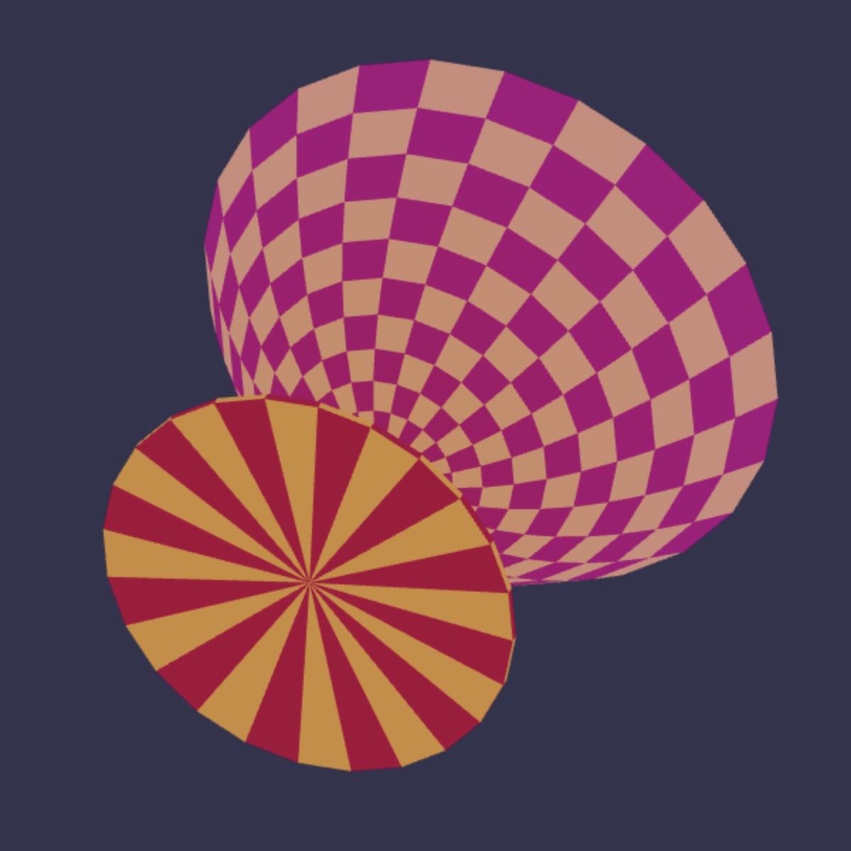
One way to create a surface in 3-space is to take a rigid curve profile and “sweep it” around in space. Imagine, for example, waving a lit baton in the air in a darkened room and taking a long exposure photo of it, like the picture above featured in a Wired article. The trajectory of the wand forms a surface in 3-space.
A surface of revolution is one formed by sweeping a curve around following a circular trajectory. A torus can be seen as a surface of revolution. Take a circular hoop and sweep it around in a circle. You’d be sweeping out the surface of a torus. A sphere is a half circle swept around in a circle. It too is a surface of revolution.
|
|
|
|
|
|
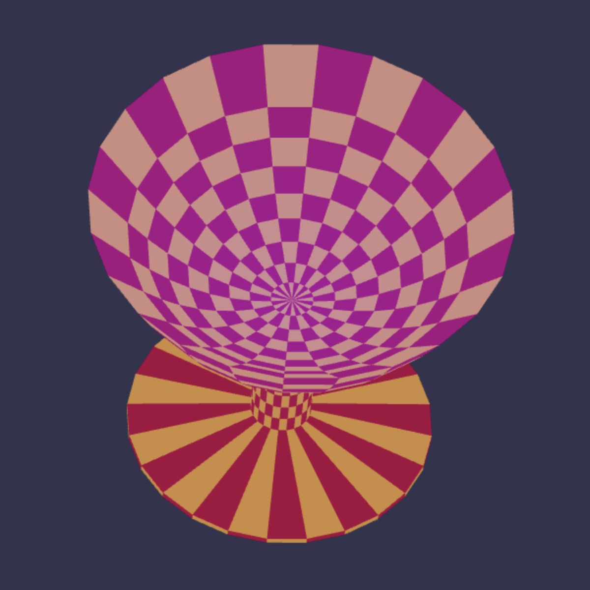
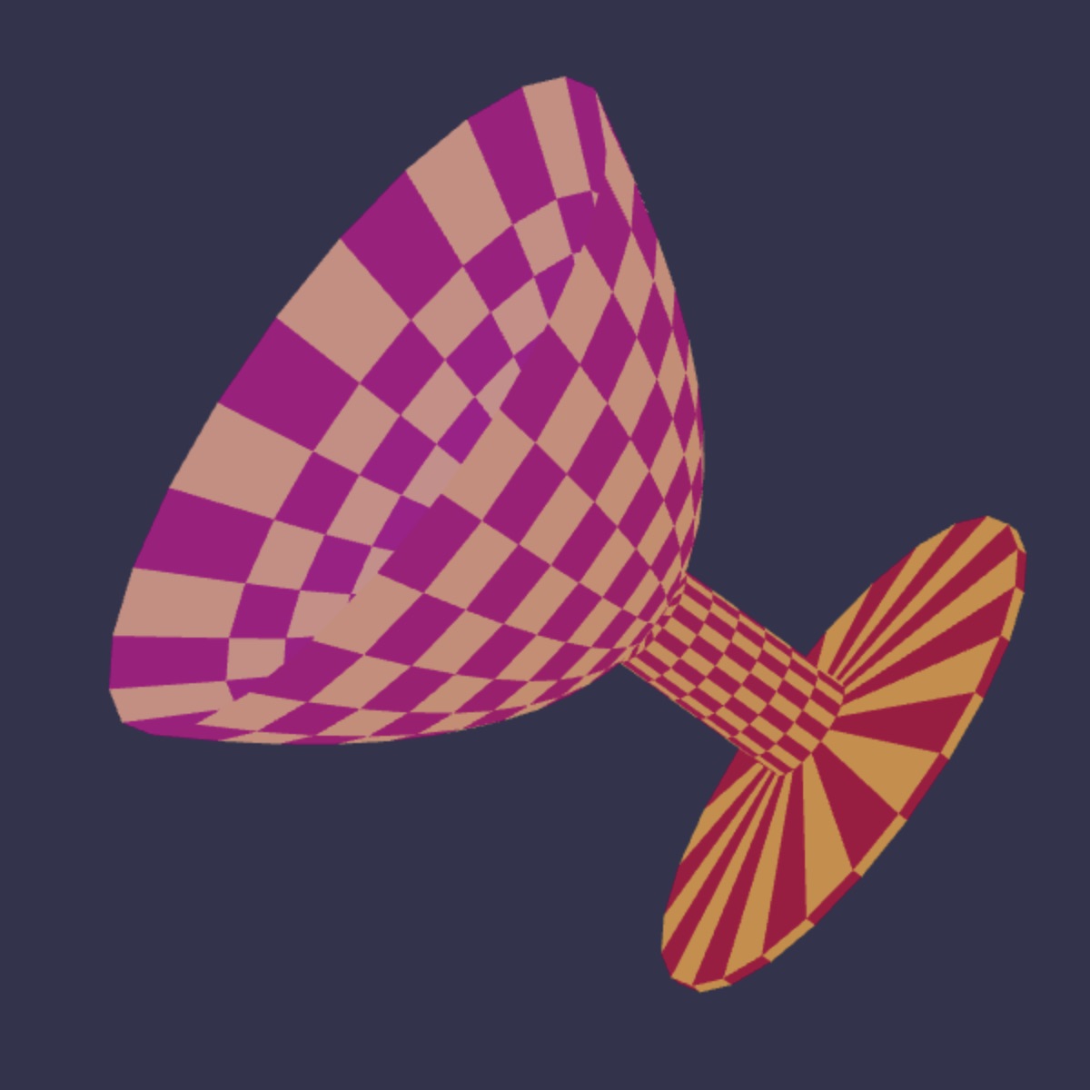
The picture above gives several views of a 3D model of a chalice depicted in WebGL. The facets that form this surface are a result of taking the profile curve of the cross section of a surface, and spinning it around the chalice center. The diagram at right is meant to depict the profile polygon of that chalice.
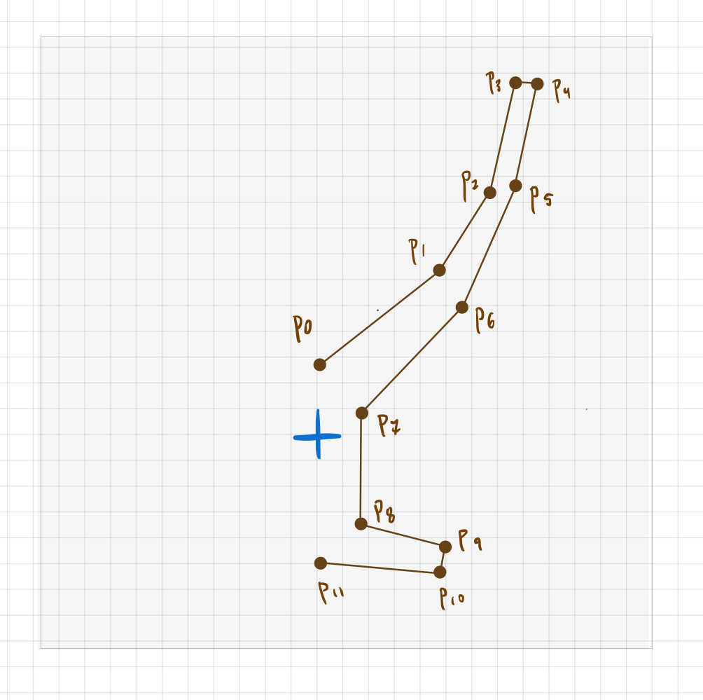
There are 12 points that define that piecewise linear curve and if they were swept 360° around a vertical axis in the center of the grid (with the pints of the profile all to the right) you would obtain a surface of a (chunky version of a) chalice. In sweeping that profile, the x coordinate of each point pipi forms a circle around the y-axis. And that circle lives in a plane parallel to the x-z plane all with the y coordinate of pipi.
Note that the chalice profile polygon shown just above right is not exactly the profile polygon used to create the 3D chalice model shown in the three views. The 3D chalice was made using a profile polygon with more points, about 30 of them. There are 10 profile points shaping the inner surface of the chalice (the part that would hold a drink), about a dozen more forming the outside, six more for the stem, and three more forming the base.
Varying the profile polygon gives you a variety of different surfaces. This variation leads us to the key function you need to write for this part of the assignment. You are to write the function:
makeRevolution(name,points)— describes (usingglBegin, etc.) a surface of revolution whose profile is given by the polygonal path given by the array of pointspoints. It names the surfacenameso that it can be drawn withglBeginEnd(name).
Each element of the Javascript array points should have an x and a y coordinate. That is points[i].x and points[i].y give each corner of the profile polygon.
Your code has one of two options for making the surface: either it is a closed surface, meaning that the first and last points of the profile polygon should be viewed as connected by an edge. Or else the first and last are not connected, as is the case of the chalice. Your code can perform the former or the latter, and you are of course welcome to add an additional boolean parameter (e.g. isClosed) so that the function can be instructed to do either. You can optionally also use a parameter for the surface’s smoothness. This smoothness parameter could effect the number of revolution steps makeRevolution would use to sweep out any surface.
To demonstrate your code, include two additional surfaces that are constructed using makeRevolution and that can be chosen among the objects of your showcase. These should be different from each other and from ones that have already been made, and not super-trivial— not, say, a cone or a cylinder, or a torus or a sphere. Some suggestions of surfaces you could make this way:
- a chalice or a fancy glass
- a pear or an apple
- a vase
- the profile of a face
Submitting your work
Upload all of your project’s files into Gradescope by the project due date.
When you hand your work in, please include every file that is needed to run the application. I’ll want to download these files and run your demo, and if you hand in all the individual files, they get packaged as a folder for me by Gradescope. By handing in the files individually (rather than as an archive file or a ZIP), I can comment on individual lines of your code within Gradescope.
You should also include a brief text file, either named submitted.md or submitted.txt, that describes the work that you did, how you did it, whether it is working, what isn’t working, and any extra things that you want to tell me about that you did or had planned to do.
Please hand in what you have completed by the deadline, even if you haven’t completed everything or the code isn’t working. You can always submit revisions later for some possible credit.