Description
Overview
Here we work to write code that performs the analysis of a mesh that yields a subdivision surface. The resulting application will have you making several of these surfaces, and testing them with a game that checks the result.
On subdivision
Subdivision surfaces are a family of schemes for computing the geometry of smoothly varying surfaces from an initial, coarsly-defined, polyhedral surface. We looked at several: the triangular mesh subdividing and averaging scheme of Loop, Catmull-Clark surfaces which work with a mesh of quadrilateral faces, Doo-Sabin’s dual scheme on quads, and the butterfly scheme for interpolating subdivision.
Several of these are a result of taking known subdivision schemes that worked with regular patches. Catmull-Clark’s is just a subdivision scheme for bicubic B-spline patches generalized to handle the case when 3 patches meet at a vertex, or 5 or more patches meet at a surface.
All the schemes are an iterative process. From an initial mesh M0M0, they provide a means for computing a mesh M1M1, then M2M2, and so on. Each succesive mesh calculation introduces (roughly) twice as many vertices, and 4x as many faces. We split the edges and faces, introducing new vertices, and we apply an averaging rule to obtain positions for all these vertices, devised as a function of the coarser vertices of the components that were split.
The mesh sequence converges to a limit surface M∞M∞ with good continuity properties. Loop’s scheme, for example, the limit surface corresponds to a parametrized surface that has C2C2 continuity. The exception is at the points whose vertices in M0M0 were connected to a number of neighbor vertices different than 6. Even at these extraordinary vertices the surface has G2G2 continuity.
In practice, like we did with curves in the last program, we terminate the subdivision after enough steps kk, and then display that smooth-enough faceted surface, depicting MkMk.
On surfaces
We work with a data structure that represents oriented surfaces. The winged half-edge mesh is a intricately linked data structure whose key component is a directed edge that links two vertices. And each such half-edge is part of a cyclic doubly-linked structure that loops around as the border of a mesh face. Also, each half-edge has a twin going in the opposite direction, and that twin is on the border of a neighboring face.
By founding all the geometry of the mesh on cyclic orderings of half-edges, we get oriented faces, and we have an oriented understanding of the neighborhood of components around each vertex, edge, and face. We can walk around the surface, and reverse our walk to return back to where we started.
Starting code
Here is the starter code for this assignment. If you download this code, you’ll will find three important code source files:
subdivide.js: description of aSurfaceclass that defines our oriented surface mesh data structure. It uses theVertex,Edge, andFaceclasses to define the components and topolgy of a mesh.cycle-subdivide.js: this code is the main driver for a javascript/WebGL application for testing your subdivision code. Along withcycle-subdivide.htmlit can be used to load several low-poly surfaces that you can subdivide. It also provides a game-like interface so that you can drive a Tron cycle on the surface, checking your data structure.cycle.js: this defines aCycleclass for the game player that drives along the surface.
The Assignment
You are to write the subdivide method of class Surface to perform Loop subdivision. I describe the data structure and how it can be subdivided in the sections below.
The class Surface
First examine the starter code in surface.js. This gives the definition of three classes Vertex, Edge, and Face. These work to represent the components of our surface mesh data structure, and they are laid out as we described in lecture. In particular, the Edge class is most central. Were this code written in C++, its instance would conform to this struct definition:
struct Edge {
    Pair<int,int>  id;     // The edge's two vertex identifiers.

    struct Vertex* source, target;
    struct Edge*   next, prev;
    struct Face*   face;
    struct Edge*   twin;

    struct Vertex* split;  // For subdivision.
};
The meaning of each of these components, excepting split, are depicted in the figure.
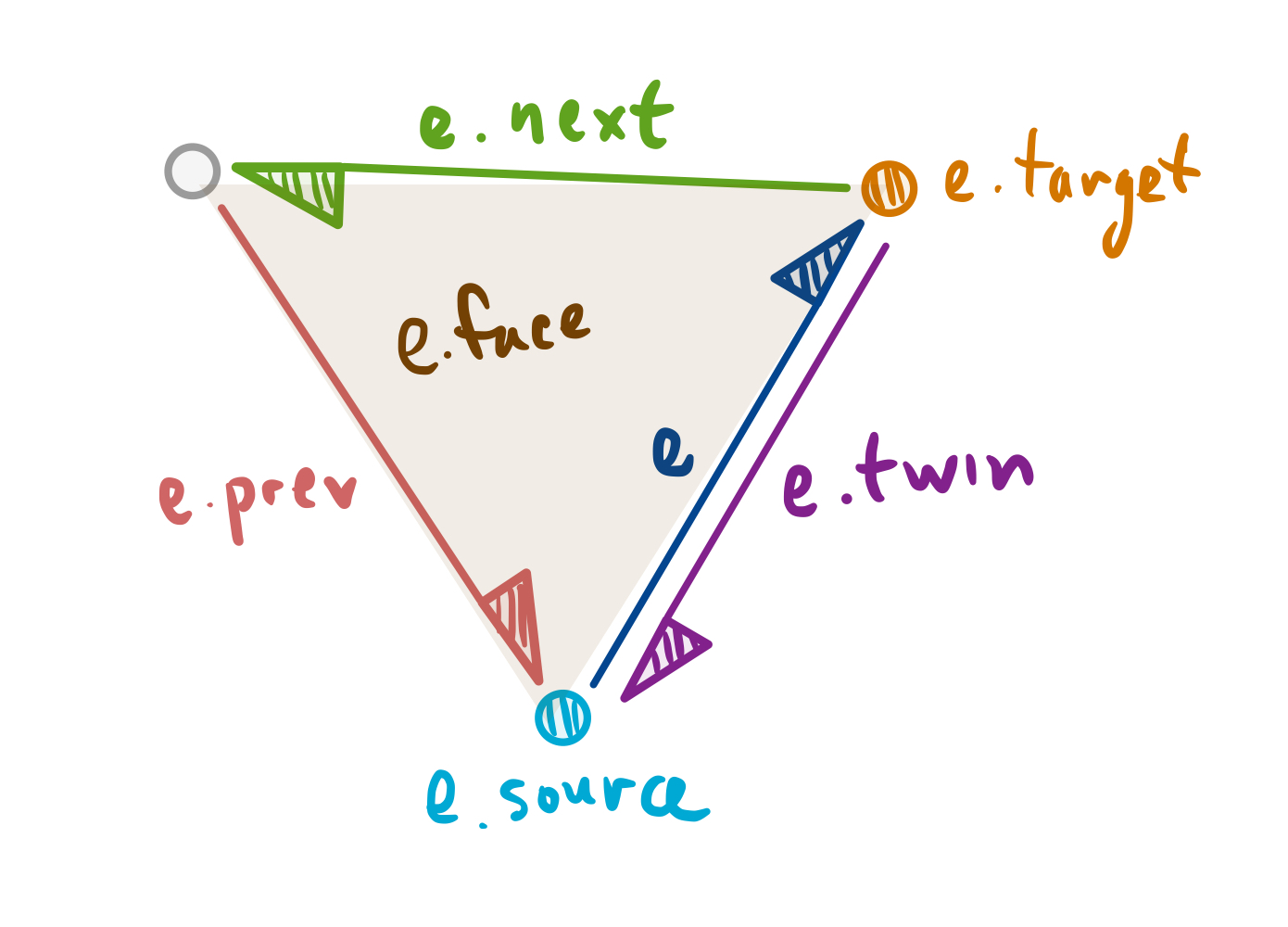
Edge e and its components.Each Edge instance e corresponds to a directed half-edge on a meshed surface. It runs between vertex e.source and e.target. To its left is its e.face. And also, e.prev and e.next are the other two edges that define that face, and in counter-clockwise order, so that the normal of the face is directed out of the page. That face has a neighboring face, and that can be found by referencing e.twin.face. The two half-edges e and e.twin define the hinge between those two faces.
A Face has this corresponding struct:
struct Face {
    int          id;    // The face number from 0 to #faces - 1.
    struct Edge* edge;
};
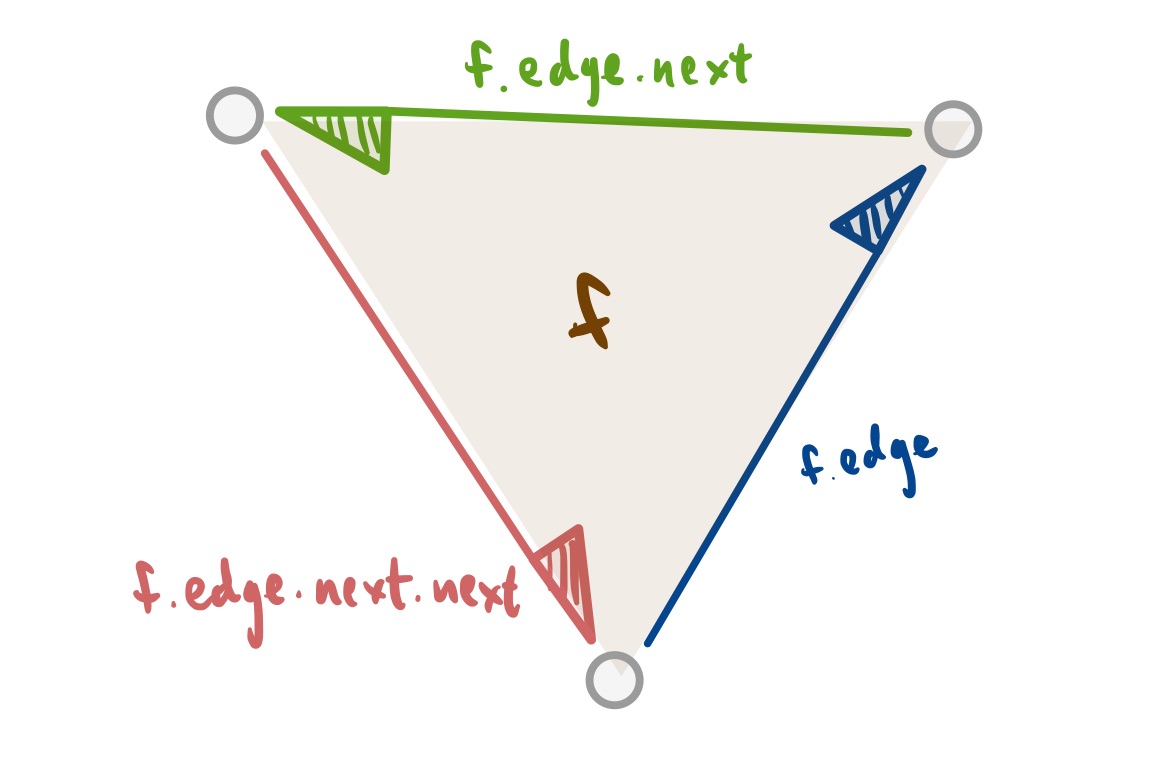
Face f.Because of the data housed in Edge, we only need one f.edge to walk around a face f. We can compute f.edge.target to obtain the first vertex on the face, and then f.edge.next.target to compute its second, and then finally f.edge.next.next.target to obtain the third vertex. Walking around the edges from a face in this way, we obtain the three vertices that make up the triangular face. We depict this edge walk around a face in the figure.
A Vertex is similarly succinct:
struct Vertex {
    int            id;       // The vertex number from 0 to #vertices - 1.
    Point3d        position;
    struct Edge*   edge;
};
We can describe the “fan” of edges around a vertex v with the sequence:
    v.edge
    v.edge.prev.twin
    v.edge.prev.twin.prev.twin
    v.edge.prev.twin.prev.twin.prev.twin
    ...
These walk around the edges of that vertex fan in counter-clockwise fashion. We depict this fan just below in this figure:
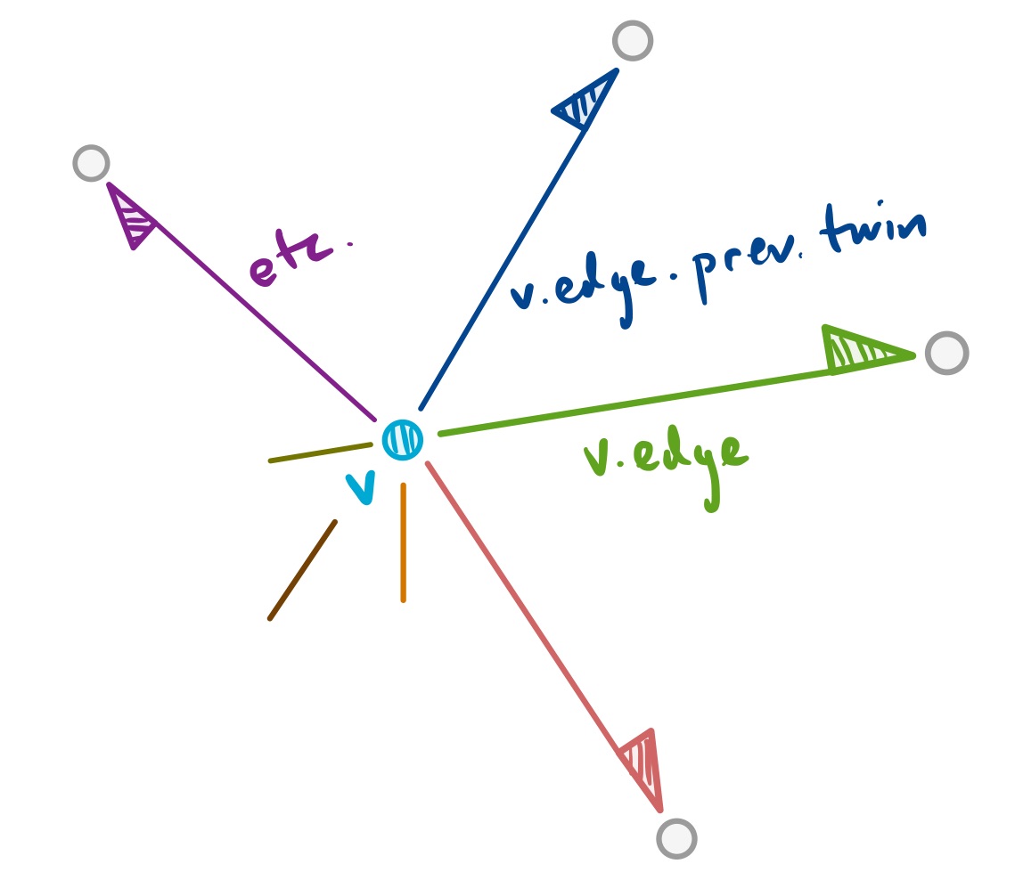
v by the edges of its fan.These three classes are put to use by class Surface defined below them. In that class, we can construct an empty surface, build all the vertices from their positions, and then stitch them all together by making faces and edges.
An example of that kind of work lives in the method Surface.read which processes an Alias/Wavefront .OBJ file. In that file format, there are a series of lines starting with v that describe all the vertex positions of a meshed surface. And then there are a set of lines starting with f giving a sequence of vertices around a face, specified by vertex number. (See for example, the tetra.obj text within the file cycle-subdivide.js.) The code for read scans in each of these vertex lines, calling the method this.makeVertex for each one. It then calls the method this.makeFace for each line describing a face.
All the stitching together of vertices and faces, by creation of half-edges and their twins, is performed within makeFace. The result is an oriented surface as specified by that .OBJ.
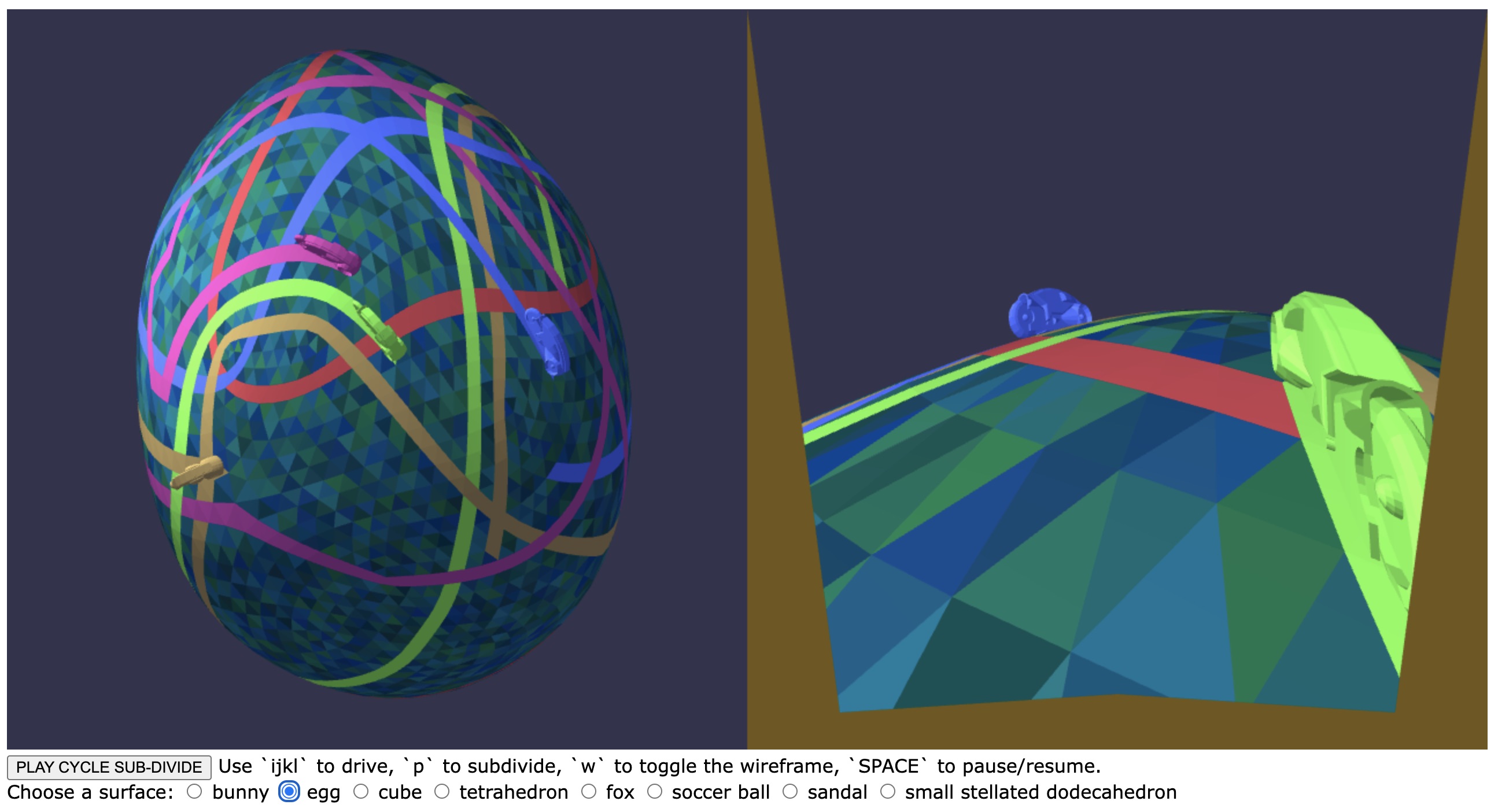
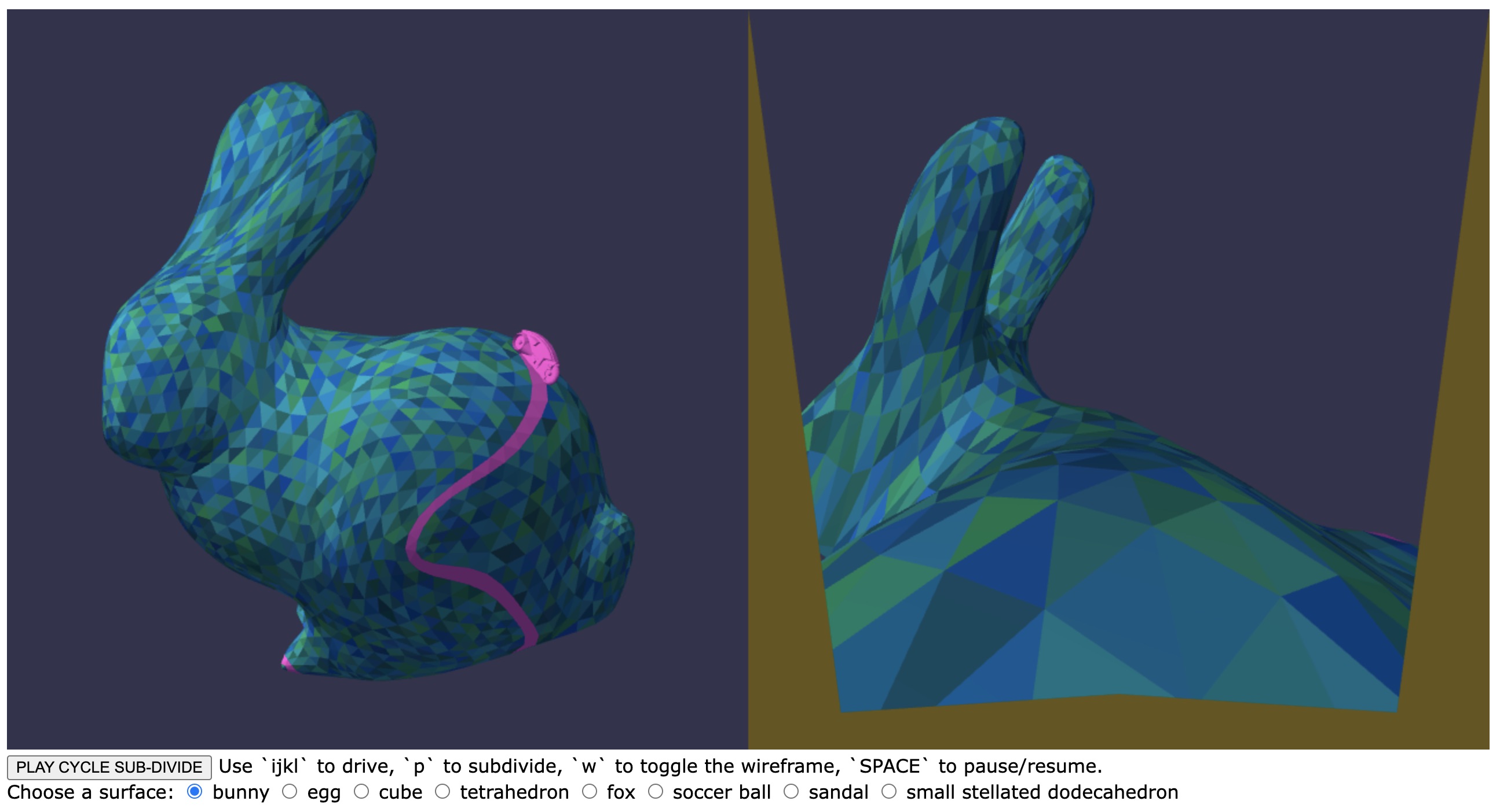
When you run the application, you can view each of these surfaces by selecting their radio button item in the surface list. If you examine the .html, you’ll see the cooresponding data as file text. Within the main cycle-subdivide.js code, the current surface object being shown is gSurface and has the name gSurfaceChoice. The surface is drawn by the Surface methods glRender and glRenderMesh. These renderings rely on the surface being pre-compiled with glBegin and glEnd. The methods glCompile and glCompileMesh.
Finally, when the program user presses p on the keyboard, the code calls gSurface.subdivide. This code should produce a new Surface that is a result of Loop subdivision. We describe this in the next two sections.
Loop Subdivision in our Code
Loop’s subdivision scheme needs to be translated into our code for Surface.subdivide. Let S be the surface being subdivided, and R be the refined S resulting from Loop subdivision. Then the method should perform these steps:
- Create an empty
Surfaceobject that will be the refined surfaceR - Create a “clone vertex” within
Rof each vertex ofSusingR.makeVertex. - Create a “split vertex” within
Rfrom each edge ofS. UseR.makeVertex. - Create all the (oriented) faces of
R, four faces for each face ofSusing the three cloned and three split vertices created in Steps 1 and 2. These faces should be built usingR.makeFacewith the correct vertices, in the correct counterclockwise order. You should use the cloned and split verticesids. - Return
R.
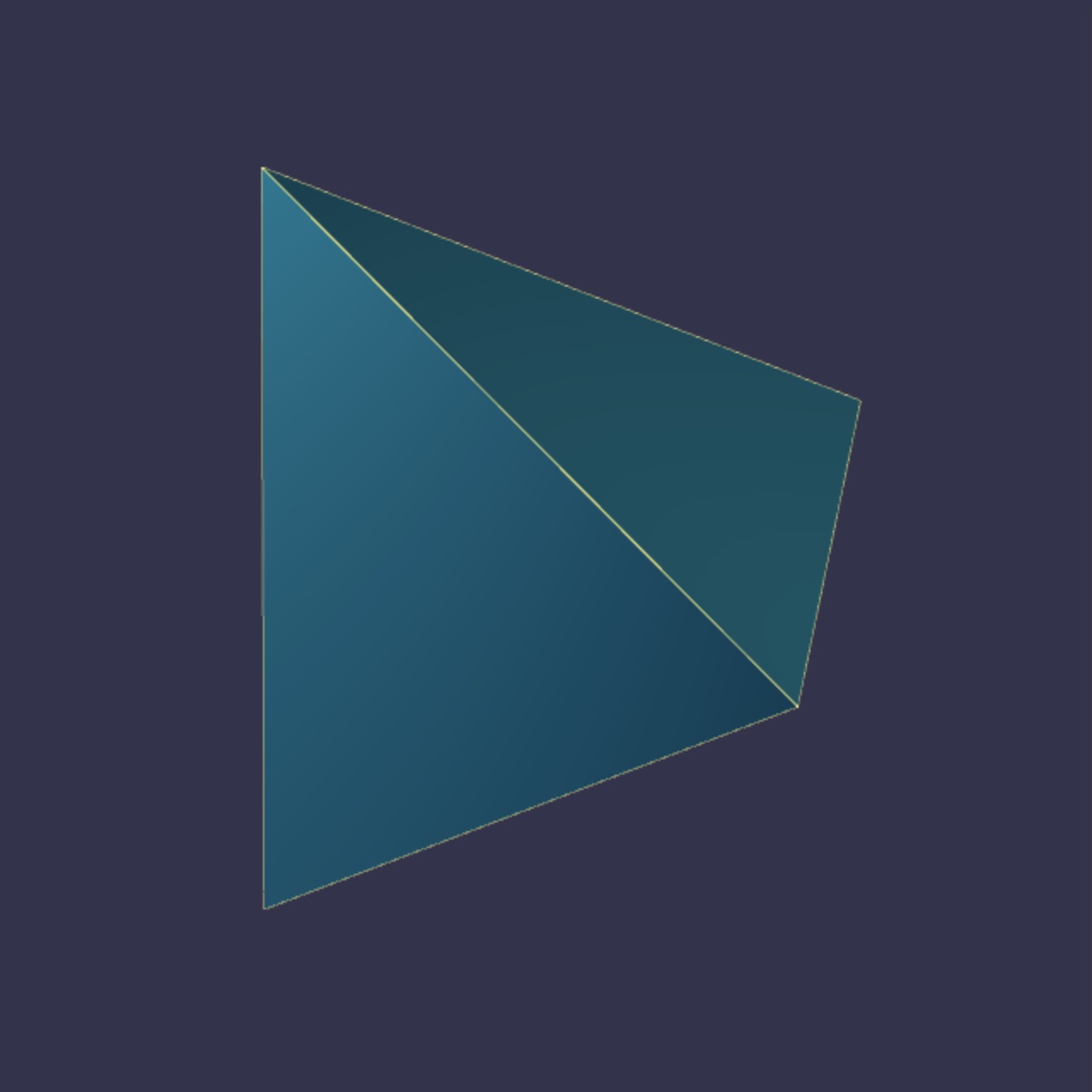
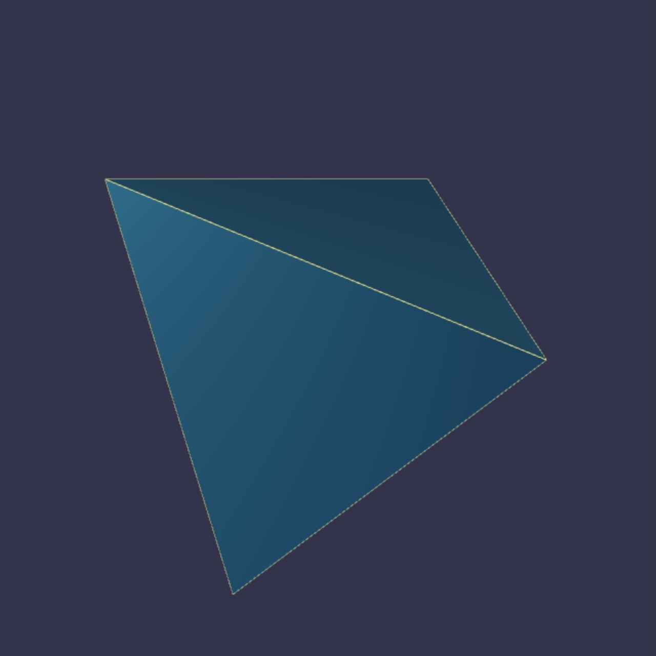
The surface R that results from this face and edge splitting is topologically similar to the picture of the tetrahedron below. Every triangular face becomes four triangular faces. Every half-edge is split into two half-edges.
To keep track of the newly introduced vertices in Step 1, so that they can be referenced in Step 3, the starter code includes an attribute v.clone for every vertex object v. When you clone a vertex v of S, you can set v.clone to be v‘s vertex clone in R.
Similarly, for Step 2, the starter code includes an attribute e.split for every half-edge Edge instance e. When you split a half-edge e of S, you can set e.clone to that new split vertex. Note that you do not want to create two split vertices for an edge. You might make that mistake if you handle splitting two twinned half-edges independently. Instead, when you introduce a split vertex, you want to associate it with both half-edge Edge objects that are being split.
Smoothing
Though the above process gives us a refined mesh with the correct topology, it does not put the clone and split vertices in the correct positions. We must also compute the positions of each split vertex and each clone vertex. The cloned vertices should not sit at the positions of the corners that were cloned. The split vertices should not just sit at the midpoints of each edge they split.
Instead, when each vertex of R is intoduced, its positition should be weighted average of the positions of nearby vertices of S.
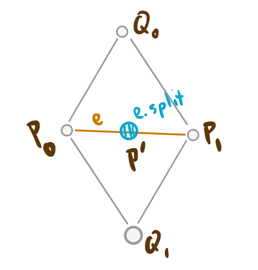
e.A split vertex position should be computed by the formula
where P0P0 and P1P1 are the endpoints of the edge being split, and Q0Q0 and Q1Q1 are are the positions of the corners of the two faces that share the split edge.
You create a split vertex in R for each pair of half-edges in S. Use a call to makeVertex and give it a position as computed above. Make sure you only add one vertex for each pair of half-edge twins.
A cloned vertex gets smoothed by taking a weighted average of its position with all its vertex neighbors.
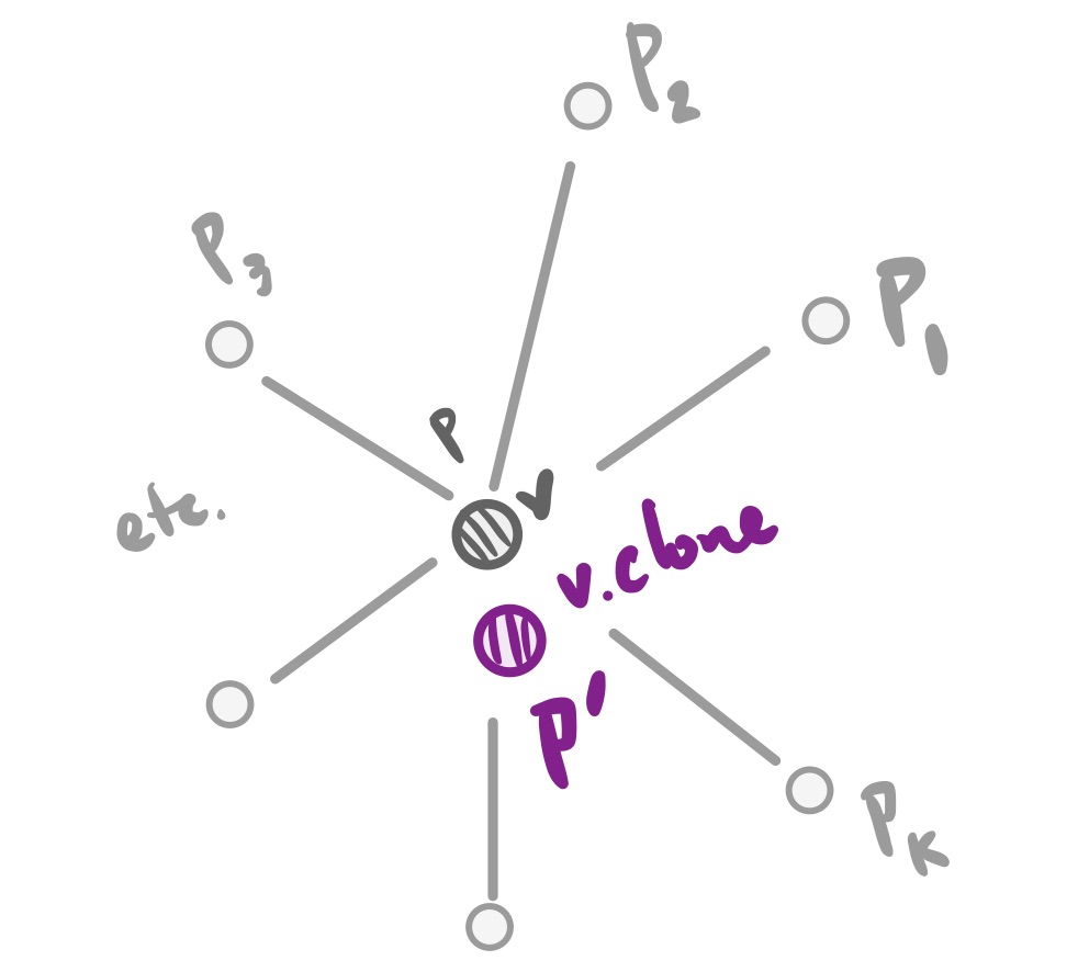
c.A cloned vertex position should be computed by the formula
where PP is the position of the vertex being cloned, and each PiPi is the position of the target of an outgoing edge from that cloned vertex. In the above, the constant ββ is computed with
You will create several clone vertices in R, cloning each vertex in S. Use a call to makeVertex giving it a position as computed above.
The Game
The starter code includes the controls and display for a mini-game that you can play to verify that your subdivision of the mesh is correct. The game mimics a scene from the 1980s movie Tron. You can drive a “light cycle” around on your surface. You press [space] to start the game and use ijkl to control the cycle’s movement.
The game’s action just performs a walk on the saurface of the object. It places a Tron cycle on the 0-th face of the surface, oriented perpendicular to that face’s first edge. It then walks from face to face and leaves a trail by painting the faces it hits. This walk is animated somewhat smoothly, with several steps making a traversal from the midpoint of the face edge to the midpoint of an edge that’s an exit to either a “left” or “right” next face. This face traversal takes several frames
The current set-up allows a player to steer the cycle left or right. By hitting the j key, the application will then choose the left exit face when it completes the drive over its current face. By hitting the l key, the application chooses the right exit face. Otherwise, the cycle makes a series of alternating left and right steps— goes to the left exit face, then goes to the right exit face, then takes the left exit face, etc.— so that the path taken by the cycle is roughly straight ahead, driven along a strip of triangles.
This actvity is represented in cycle.js, and the behavior is described as the methods of a class Cycle. The main application code in cycle-subdivide.js just invokes these methods. It also calls its methods for rendering the cycle on the surface, and for rendering the surface from the perspective of the player sitting on the surface.
Steps for Completing subdivide
I recommend completing the code for subdivide in two stages:
Stage 1: get the topology correct
In the first stage you introduce all the clone and split vertices for the new surface, stitch them together, and return that surface without smoothing their positions. When you get this working correctly, your refined surface meshes will still have their original shape, just with more and more triangular patches.
Below shows images of the tetrahedron before and after performing a simple Stage 1 subdivision, once and twice.
|
|
|
|
|
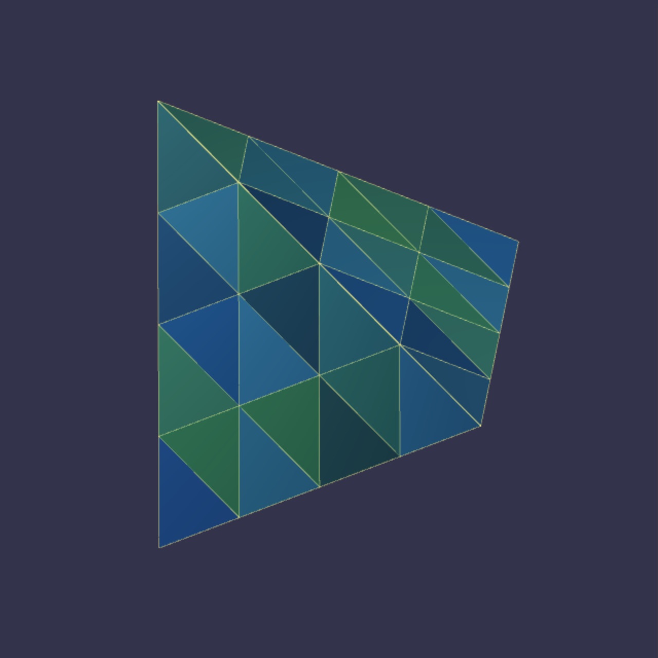
|
Note that you can get the positions correct— cloning the vertices, computing simple midpoints when you split edges— but not actually link up the components correctly. The way this would likely manifest itself is that you’ll have mutliple, redundant copies of some components, and you may have components that fail to be linked up.
You can use the Tron game to test your work. Hopefully the light cycle drives around on your subdivided surface just fine. If so, that probably means that you stitched the elements of the surface together correctly. If instead there are bugs in how you constructed the subdivision, the code that moves the cycle will crash. An attempt to move the cycle from one element in the mesh to another code might face the consequences of Javascript requesting info about a null reference to a neighboring object.
You might also find it useful to write code that separately verifies that all the vertices, edges, and faces are in proper relation with each other. (E.g. e.twin.twin == e, v.edge.source == v, etc.)
Stage 2: get the smoothing correct
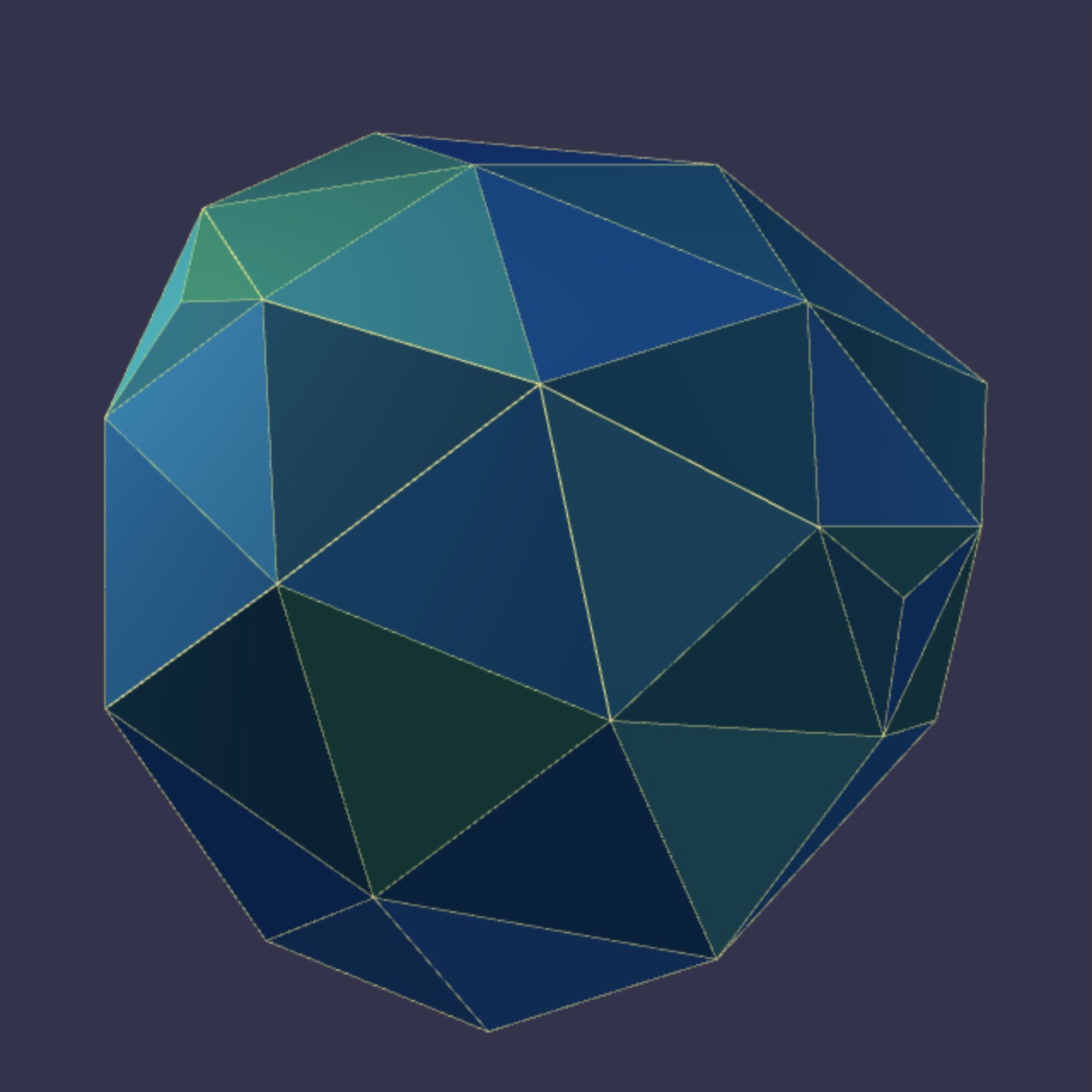
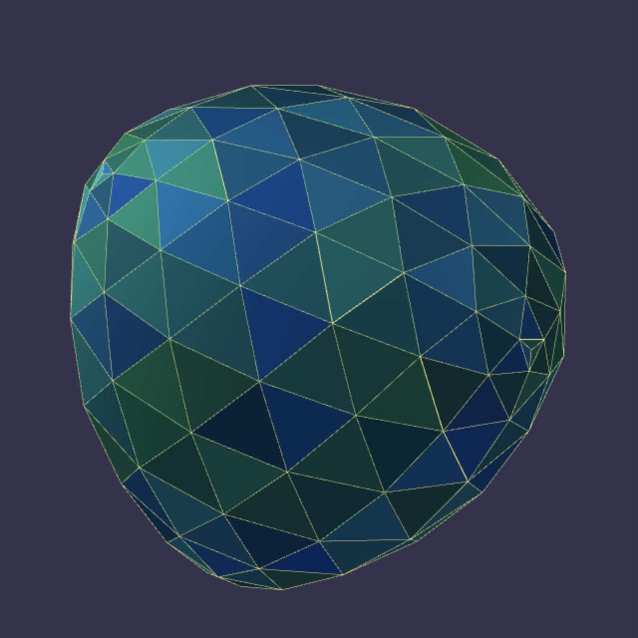
In the second stage, figure out how to compute the smoothed vertex positions. It is here that you might get some strange, but viewable, errors. If you use the wrong formula, or select neighboring vertices incorrectly, the surface geometry can go quite awry.
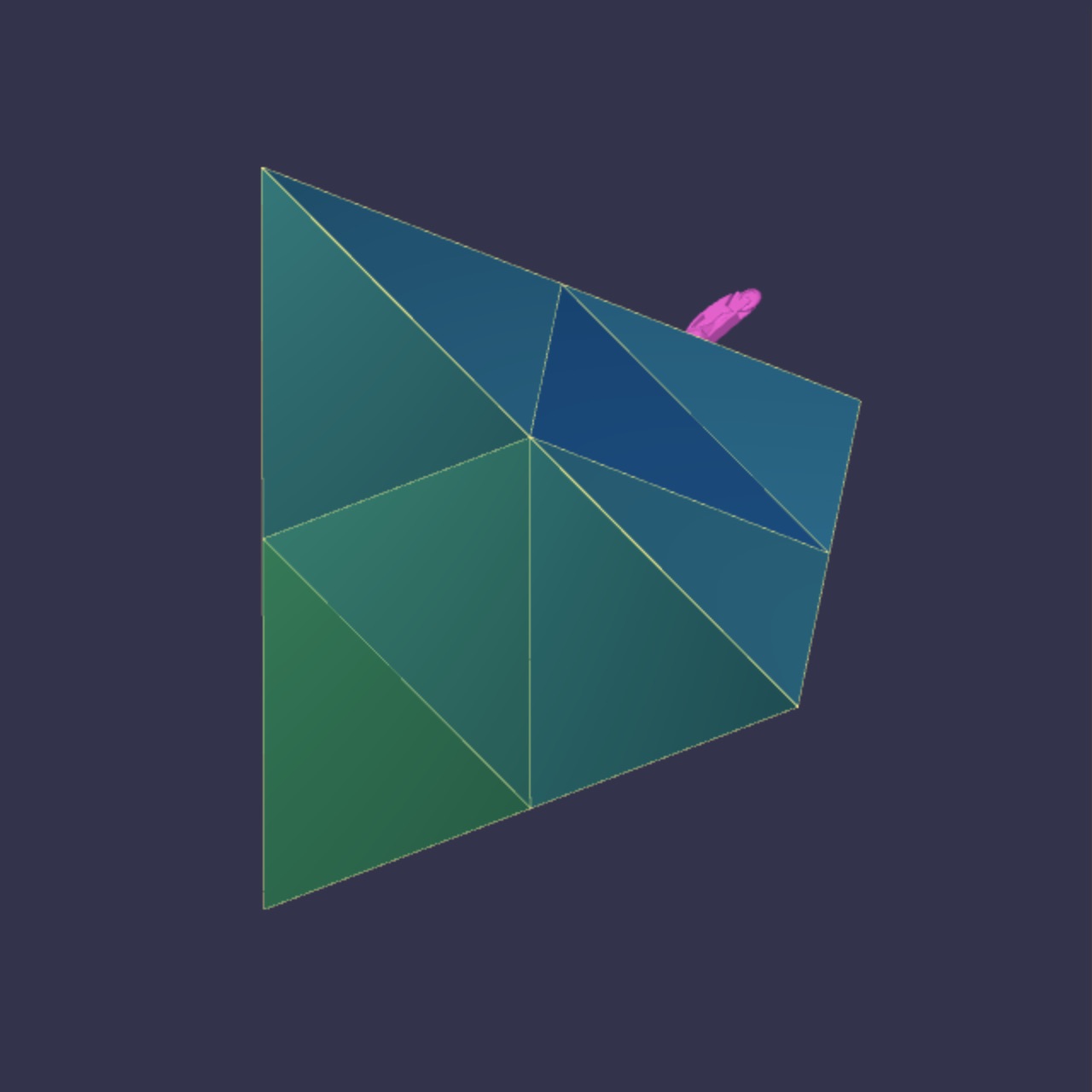
Below are images of the tetrahedron, subdivided once, twice, and thrice.
|
|
|
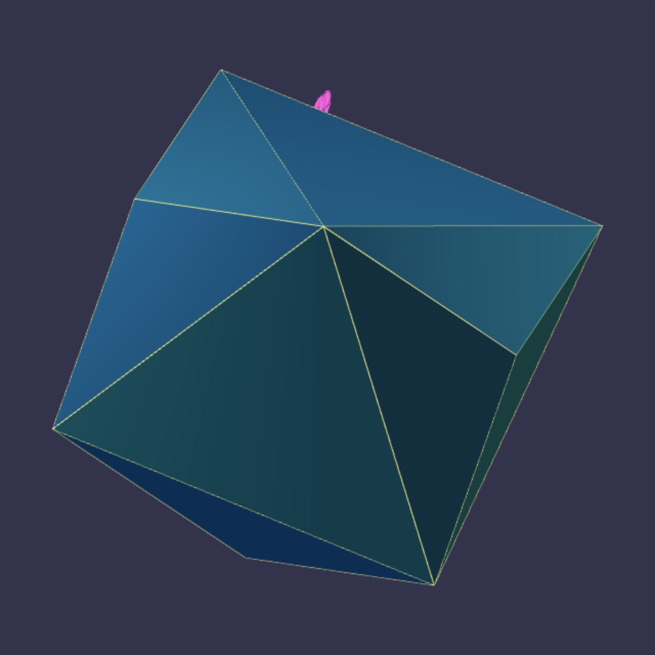
|
|
|
|
|
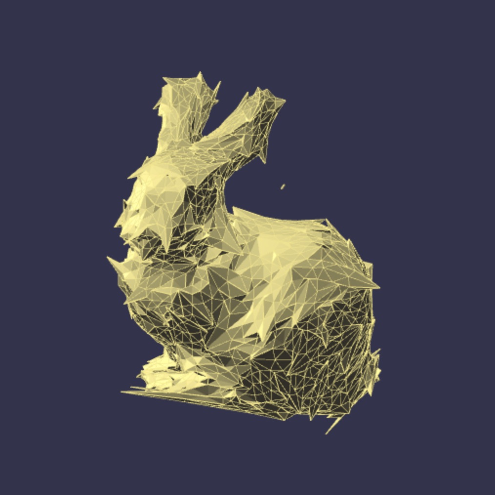
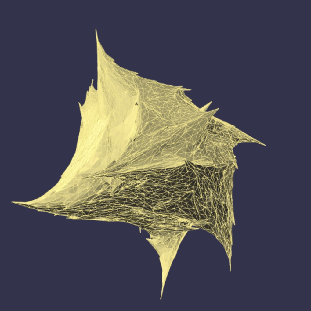
Mistakes here are usually much easier to spot. For example, the pictures below show what happened when my code used the incorrect vertex locations to perform smoothing, It also had the wrong stopping conditions in the loop around each clone vertex.
|
|
|
|
Summary and Hand-In
There is just one hand-in for this assignment. Hand in a working version of the subdivision code, having correctly completed Surface.subdivide. You should be able to complete this code in less than a week, maybe with three evenings of attempt (first attempt: Stage 1; second attempt: buggy Stage 2; third evening: everything fixed). It’s about 40 lines of code and most of the trickly work is handled by makeVertex and makeFace. Hand in screenshots of your subdivision code working on a complex object, say, the fox. Also include a screenshot of the subdivided object after the cycle has painted quite a bit on it.