

Description
Overview
|
|
|
Throughout this semester, we learn methods for producing photo-realistic renderings of virtual scenes. These methods do their best, given computing resource computations, to model the physics of light transport, of how real materials reflect, absorb, and transmit light, and of how cameras capture the light of a scene to record an image. They rely on the mathematics we have covered recently for tracking and relating geometric points and directions in 3-space.
For this assignment we take a different approach to computer rendering that was used in earlier graphics systems, before photo-realistic rendering was technologically feasible. We write code that produces line drawings of geometric objects. The results are not photo-realistic, but the methods use a lot of the same principles, and certainly many of the geometric calculations, used in photo-realistic rendering.
To make our drawings of 3-D scenes, we use ray casting to compute a perspective projection of what the camera sees, depicting objects as wireframes but with hidden lines removed. Your completed code will take as input a “walk-through” of a scene made up of objects, given as a path of camera positions. It will compute a rendering of the walk-through as a “flip book”— a series of pages of flat line drawings that can be flipped through to animate the walk. In doing so, you’ll practice using the affine geometry primitive operations defined in geometry-2d.js and geometry-3d.js which define point and vector operations in 2-D and in 3-D. These, along with the mesh specifications given by each placed SceneObject, allow your code to turn the 3-D scene into a PDF document.
Below I take you through several parts of the project, orient you to how everything is meant to work together, and then take you through the steps you can use to complete the project.
Written part
The programming requires coding of a few geometric operations, but you’ll want to first work out these operations on paper before you write their code. I’ve packaged these operatsions as a set of written problems you should solve, and hand in, so that you can make progress and plan for the coding.
Downloads and starting code
- Here is the starter code for this assignment.
- Here is the written part of this assignment.
- Here also is a PDF of a scene generated by one of my solutions to the assignment.
Playing with the walk-through editor
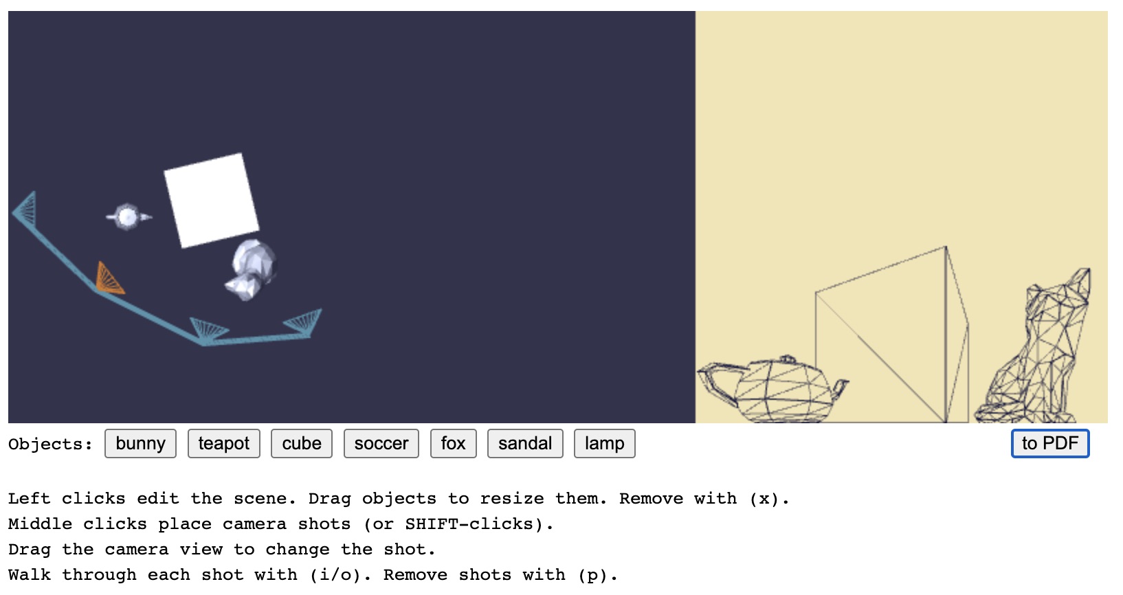
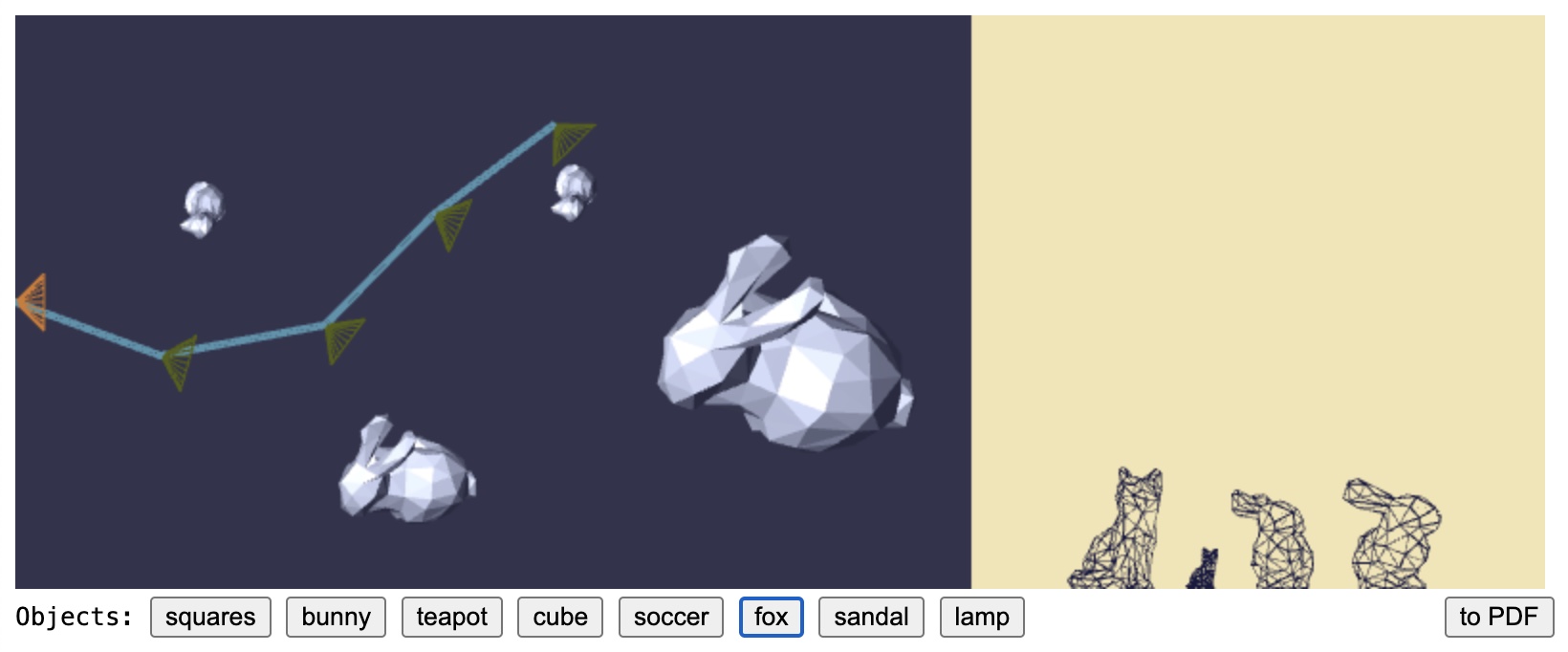
If you load flip-book.html within your browser, you will see a user interface as shown in Figure 1. The WebGL canvas is split into two parts: the left dark blue part allows you to place several objects on the floor of the scene, and also to lay out a path of camera shots that walk through the scene. Objects can be placed and dragged with mouse clicks. Cameras can be placed and moved by clicking and dragging the mouse with a press of the middle mouse button (or, alternatively, by holding the SHIFT key while you click).
The right part of the display shows a square region of the scene from the currently selected camera’s perspective. It shows the objects as black wireframe meshes with hidden lines removed. This is just using WebGL’s standard hardware algorithms for doing that work. It serves as a preview of what your code will render as PDF.
You’ll notice that each camera is sitting on the floor of the scene, at the same level of the bases of the objects, and looking in a particular xx–yy direction along the floor (the zz direction is upward). You can change the direction of a camera by clicking on the preview square and dragging its perspective left and right. The editor limits this view change to being a pan around the up direction of the camera. The camera’s view direction can only be rotated within the xx–yy plane.
The buttons sitting just below the scene editor allow you to select which object you’d like to place. There are several faceted objects, including lower-resolution versions of the Stanford bunny and the Utah teapot. The descriptions of these objects are embedded within the HTML as Alias/Wavefront .OBJ files. When the user presses one of these buttons, the code loads the mesh description of that object.
Once a user sets up a scene and a series of shots, they click the toPDF button to set the wheels in motion— to run the code that you need to write— that leads to your browser downloading a PDF document of the walk-through, one that was just freshly computed by your code.
Starting code
In the code’s current state, clicking toPDF will perform a simple rendering of the scene as a collection of “see-through” wireframe meshes, and only using an orthographic projection looking directly to the right from each of the camera shot locations. There will be a page for each camera shot, but the scene will look nearly the same for each one because of the orthographic projections that look directly to the right.
Your assignment is to change the code to produce the proper images in the PDF file. When completed fully, you’ll have a sequence of PDF pages that look like the preview shots of the editor.
Tester code
In addition to the WebGL application run by flip-book.html that runs the code in flip-book.js, the starter code folder also contains two other WebGL applications that share use of the code you write. You can use these applications to test and debug your code without needing to do so within the flip-book application. They are:
segment-intersect.htmlandsegment-intersect.js: editor that uses your code to compute the intersection of two line segments laid out in 2-Dfacet-hit.htmlandfacet-hit.js: editor that uses your code to compute the intersection of a ray with a triangular facet, all living in 3-D space.
These use the same critical code you’ll write to complete the toPDF code. They are described briefly in two appendices at the bottom of this page.
The Assignment
Modify the toPDF functionality of the web application so that it performs a proper perspective drawing of the scene’s objects based on the specified camera shots. Each page of the PDF should mimic the WebGL rendering by judiciously marking lines onto the pages of the PDF. This coding can be done within the files walk-thru.js using some supporting geometric functions you’ll write in walk-thru-library.js. In particular, the editor program makes a WalkThru object whose class definition is in walk-thru.js. The editor calls the walk-through object’s toPDF method to assemble the PDF document.
You’ll write the code used by this toPDF method, particularly its use of a collection of object placements that get built as SceneObject instances to provide each object’s geometry, and its use of camera Shot objects that get built as SceneCamera instances to provide the calculation of a perspective projection to take a snapshot of the scene.
Below I take you through a candidate solution for the project, talk about the supporting code that you’ll rely upon, and then give you strategies for completing and debugging your code.
Towards a solution
There are several places in the walk-thru.js code that I’ve marked with several // TO DO code comments. Finding these will orient you to writing your solution code. The description below walks you through that work.
|
|
|
Let’s take a guided tour through coding up the WalkThru.toPDF method. For each step of this guided tour, we will work with two scenes. One contains a single cube. The other contains two triangular hinges, one in front of the other. This is a result of using the squares button to select and place an object.
Step 1: camera frame
The first thing you will want to get correct is computation of the perspective projection of all the object’s vertex points. These are the corners of every object that live in the 3-D scene. Every vertex v has a v.position attribute of type Point3d. You’ll need to determine a Point2d location for each vertex. Your code can loop through all the vertices of each scene object and apply a perspective calculation for the camera’s view.
The projection calculation should be provided by a SceneCamera object’s project method. A scene camera instance is built by specifying the center of projection, a direction that the camera faces, and a general direction upward. These can be used to construct an orthonormal frame— the center forms the frame’s origin, and three other directions provide an orthonormal basis— that can be used to provide the projection.
There is a class SceneCamera in walk-thru.js that provides a template for this coding. Right now, its constructor and its project method have bogus code, just to make the starter code run. You’ll want to fix the constructor code so that it computes something like the following:
c.centeris a point in 3-space where the projection frustum’s cone emanates. This point is the source of any ray that you cast to a 3-D location in the scene.c.intois a unit direction into the scene. This direction serves as the normal to the sheet of paper where we will project our objects’ geometry to make our drawing.c.rightandc.up: these should serve as the 2-D orthonormal basis for expressing the coordinates of the points when projected and drawn on the sheet of paper.
These should be computed from center and toward which are provided to the constructor from the shot editor GUI. There is also an upward direction. For this code, it is just given in the zz-drection. It is aligned with the central axes of each scene object. Each object base sits in the xx–yy plane at z=0z=0, and their central axis points upward. The toward direction, as currently given by the GUI, is already perpendicular to the zz-direction and so has a zz component of 0. The center of projection provided by the GUI lies on the floor, and so it also has a zz component of 0.
Once you’ve completed this coding for Step 1 you have computed the orthonormal frame of a scene camera for its perspective projection. These calculations are the ones you devise for Problem 1 of the written portion of the assignment.
Step 2: projecting vertices
Now that we’ve written code for computing an orthonormal frame for each SceneCamera, the next step is to compute the perspective projection. We take the 3-D location of each vertex of an object on the scene and “splat” it onto a virtual sheet of paper of the PDF. When you’ve completed the coding for Step 2 you will produce pages of drawings, one page for each camera shot. The objects will be “see through” wireframes, not faceted surfaces. Because they will result from a perspective calculation, they will be warped with foreshortening (etc.) rather than what was obtained with the orthographic projection.
Sizing up the perspective projection
Let’s work through the set-up your code will face with each SceneCamera when it performs the perspective projection. Let’s first be more clear about the coordinate systems of the scene editor. In the figure below we have a scene littered with two bunnies and two foxes. The leftmost camera location is selected, and it is pointing directly right. We see two foxes on the left field of the shot, and two bunnies on the right field of the shot. The two bunnies look to be the same height in the shot, but they are different sizes. The larger bunny’s dimensions are about twice that of the smaller bunny’s, but it is also about twice as far away from the camera. This is a consequence of the mathematics of the perspective projection.
If you were to inspect the 3-D points of the camera locations and the scene objects, you would learn that the origin point (0,0,0)(0,0,0) sits at the left part of the scene editor, mid-way up the left side of that rectangle. You would learn that the positive yy-axis is along that left side of the scene editor rectangle, with positive yy pointing upward. You would learn also that the xx-axis is aligned with the top and bottom edges of the scene editor rectangle. The positive xx-axis points directly to the right, perpendicular to the left side of the scene editor rectangle. Then finally the positive zz-axis is pointing directly out of the computer screen. Within the scene editor, we are looking down onto the objects in the negative zz direction. The scene editor rectangle is two units tall. This means that the top-left corner is at (0,1,0)(0,1,0) and the bottom-left corner is at (0,−1.0,0.0)(0,−1.0,0.0).
This means that the first camera has a towards vector of (1,0,0)(1,0,0), an upward vector of (0,0,1)(0,0,1), and its center point is at (0,0,0)(0,0,0). The second camera has a center of about (0.4,0.2,0)(0.4,0.2,0). With a perspective pointing slightly right of the view of the first camera, the second camera has a towards direction of about (0.91,−0.41,0)(0.91,−0.41,0). This vector is tilted down a little off from the xx-axis’s right alignment.
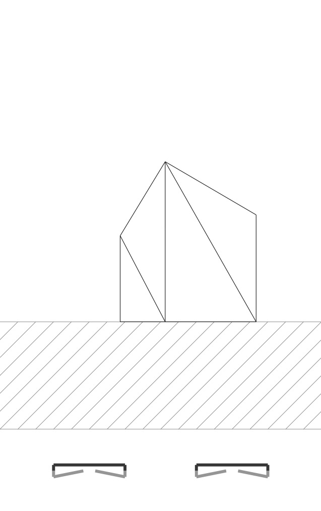
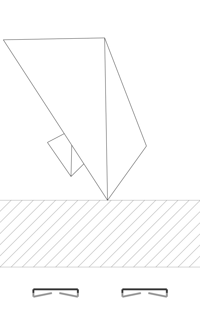
Now let’s figure out the “view frustum” you’ll use for the perspective projection. The figure below shows a different scene. I’ve placed two cubes into the scene. I’ve lined them up and sized them in a way such that they both nearly cover the square page in the shot preview. They nearly cover the whole 54mm x 54mm square of the paper.
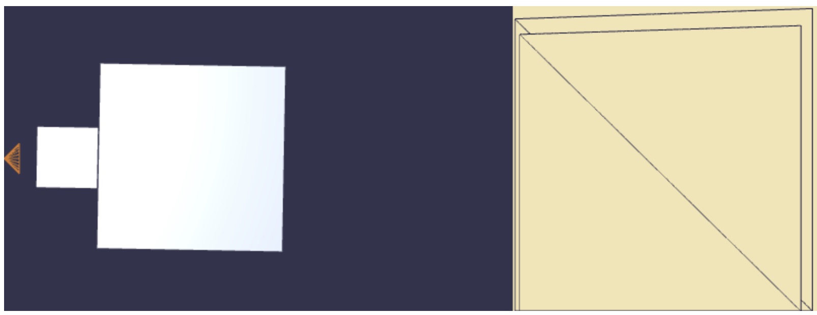
If you look at the two camera-facing sides of the two cubes within the scene editor, their corners are aligned along rays that emanate from the camera’s center. This means that, within the perspective view, the vertical edges of their camera-facing corners form the left and right side of the view’s frame. This tells us that we have a perspecive projection in the xx-axis direction whose field of view is 90°. That is, the view frustum is a “right” pyramid— a pyramid whose top point’s angle is a right angle.
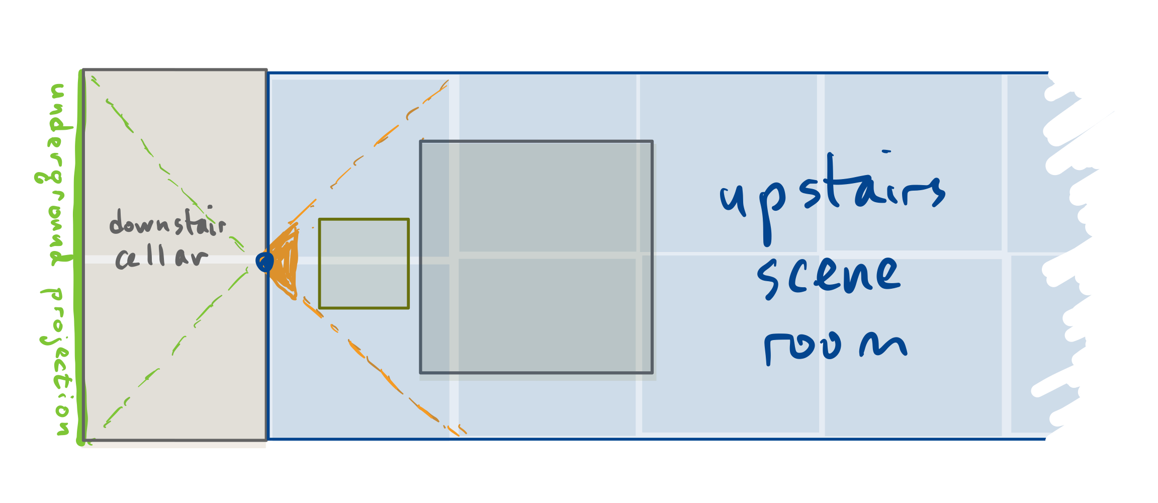
It turns out that this perspective projection is the one that results from building a 1 × 2 × 2 basement cellar room and drilling a hole in the floor of the scene room right where the camera sits. The light from the scene would be projected back through the hole onto the cellar’s back wall (see Figure 5). Your code is tracing the objects when their image is projected onto that back wall.
Ray casting into the scene
Let’s figure out the work of that projection using ray casting. When you project the scene onto paper, you use the right, up, and into vectors as the axes of a left-handed orthonormal frame. This allows you to compute, for each vertex in the scene, its depth from the camera, and also its position on the paper.
Problem 2 on the written part asks you to figure out this calculation using the affine vector and point operations we’ve discussed in lecture. And then you use the Vector3d.dot, Point3d.minus and other operations as defined in geometry-3d.js to write this calculation as code.
In my solution to this step, I produce a primitive Javascript object for a result of SceneCamera.project. That result contains the following info:
result.projection: an instance ofPoint2dwhosexandycomponents would live within [−1.0,1.0]×[0.0,2.0][−1.0,1.0]×[0.0,2.0] in order to be seen on the square page. This is the projected location of the vertex.result.depth: the perpendicular distance where the vertex sits away from the camera.result.point: the original 3-D location of the projected vertex, aPoint3dinstance.
You’ll see in the starter code that SceneCamera.project is called several times within the loop of SceneObject.projectVertices. Within that method, we build a Javascript Map that associates to each object vertex its projection information onto the 2-D page. This Map information is kept around to be used later in steps 3 and 4 described below.
Results
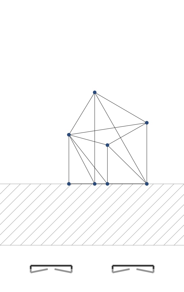
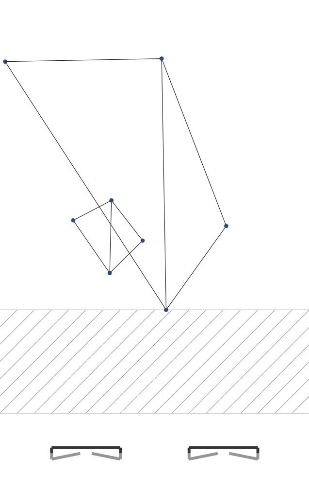
When you have completed this step correctly, if you draw each vertex’s projection with a small circle and each edge as a line connecting these two dots, you will get PDFs like these:
|
|
|
For the cube object, the 6 sides are made up of triangle pairs. And so we are seeing the diagonals of many of these faces, including the hidden ones. For the hinged square scene we have two pairs of triangles. We are seeing all the edges here too.
These figures rely on calls to methods of the document object passed to WalkThru.toPDF. This object is provided by the jsPDF package. These functions draw figures on a credit card-sized page:
document.line(x1,x2,y1,y2): places a line from/to the given points. The coordinates are in millimeters from the upper-left corner of the document.document.circle(x,y,r,"F"): places a filled disk centered as a dot whose radius isrin millimeters.document.setFillColor(r,g,b): sets the color for the dot using the given RGB components, but in the range0through255instead of the range0.0to1.0that WebGL uses.document.setLineWidth(w): sets the width for the line in millimeters.document.setDrawColor(r,g,b): sets the color of the line.
We make all these calls within the code for SceneEdge.draw, and this is the method code you’ll now modify for steps 3 and 4.
Step 3: segment intersect
In Step 2 just above, you ended up drawing all the edges of each object, including parts that are hidden by other faces. Let’s now work to correct this by performing the calculations needed to break up an edge into a mix of hidden and visible line segments. We’ll do this by looking at the intersections of all the projected edges. These intersection points serve as the potential “breakpoints” for depicting the edges.
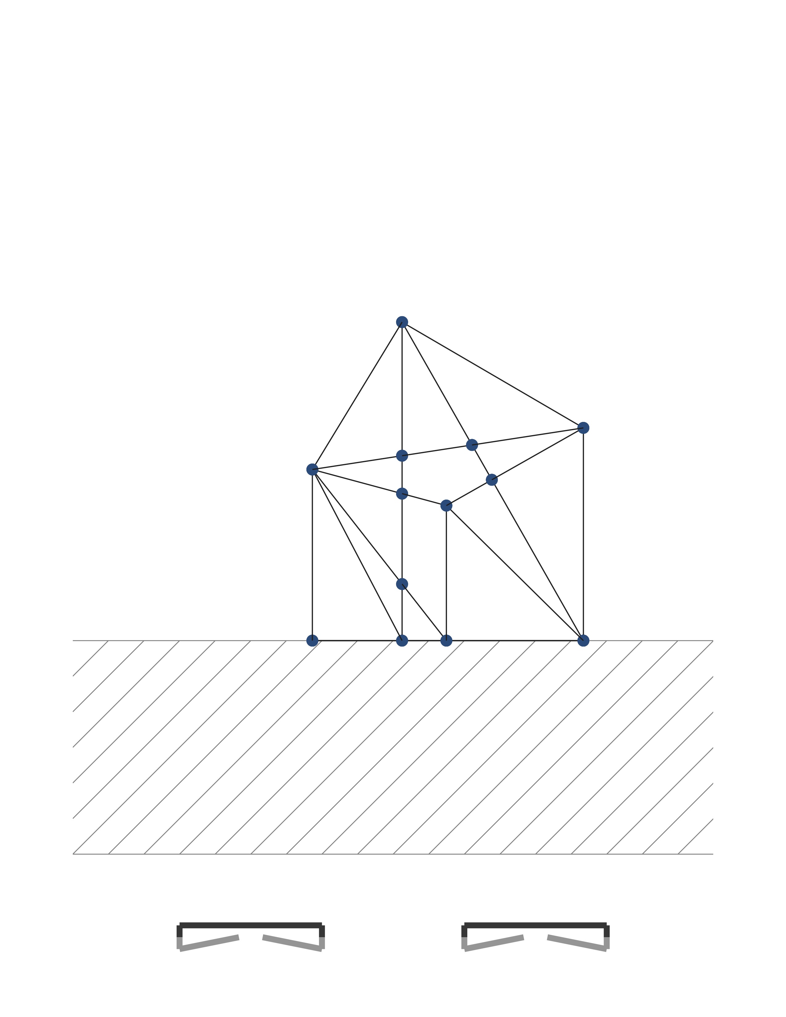
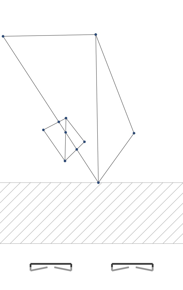
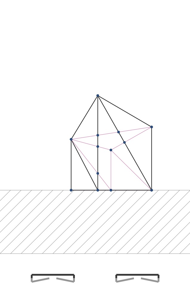
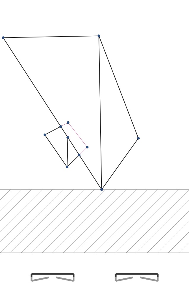
If part of an edge is obscured in its middle by some face, then that part of the edge shouldn’t be drawn. The start and end points of that occluded segment of the edge will occur where that face crosses the edge from the perspective of the camera. Consider the pictures below. I’ve added dots where edges cross. If you compare figure 2b with figure 7b, you can see that the right half of the smaller hinged square is obscured by the left part of the larger hinged square. The three edges of the smaller hinge that cross the edge of the larger hinge should only be drawn part way, up to that crossing edge.
In other words the left edge of the larger hinged square makes three breakpoints on three edges of the smaller hinged square. Each of those three edges should only be drawn to each breakpoint.
|
|
|
Step 3, then, should compute all the breakpoint locations along an edge so that you can draw the edge correctly in Step 4. The provided code structures this using a method SceneEdge.breakpoints. It should return an array of values between 0.0 and 1.0 where these breakpoints occur. If an edge spans points P0P0 and P1P1, then the breakpoint occurs at value ss whenever there is a breakpoint located at
Let s1,s2,…,sns1,s2,…,sn be the series of breakpoint values for an edge. We sort them so that
These tell us that when we draw the projected edge, it is divided into n+1n+1 segments according to these nn breakpoints. And, to consider drawing the edge, we run through those n+1n+1 segment pieces from P0P0 to P1P1.
Problem 3 on the written part asks you to figure out the calculation for finding the intersection between two line segments in 2-D space. You should work to formulate this intersection using only the point and vector operations we discussed in lecture, ones that are available in the geometry-2d.js library with classes Point2d and Vector2d.
Note that It wouldn’t be hard to do this calculation using coordinate calculations, and you can do that to just get the code working. For full credit, however, you need to devise a scheme that uses the “coordinate-free” geometric operations.
Write this intersection code within the function segmentsIntersect in the file walk-thru-library.js. This function can then be tested on its own using the segments-intersect.html application described in Appendix 6.2. And then, ultimately, you will call segmentsIntersect within the code for SceneEdge.breakpoints, looking for all the edges that cross any particular scene edge when projected in 2-D. The method SceneEdge.breakpoints is ultimately called by SceneEdge.draw so that it knows how to draw that edge.
Results
To see this all working within the flip-book.html application, have the code for SceneEdge.draw just place dots at all the breakpoints along an edge, but still have it draw the whole edge. When you have completed this step correctly, you will get PDFs like those shown in figures 7a and 7b above.
Step 4: drawing a segment
Now that we’ve marked out all the intersections, we’ll now actually want to draw an edge as a sequence of only its visible segments. Below, I’ve modified the prior figures to illustrate a method for doing this.
|
|
|
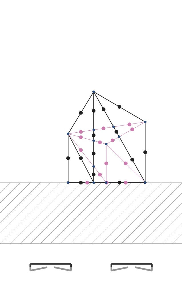
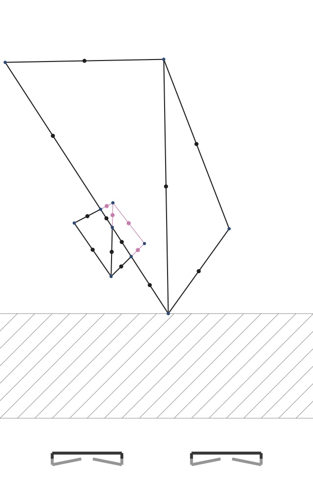
Here you see clearly that edges can have a series of included (black) and excluded (pink) portions. The excluded portions are those obscured by some face that’s sitting closer to the camera.
We scan through the segments that form the edge. These segments are defined by the breakpoints we found in Step 3. For each segment, you cast a ray from the center of projection to each segment to see whether it should be drawn. If some other triangle sits closer to the camera, then that subsegment should not be drawn (shown above as pink). If there is no triangle hit between the camera and the segment, then we should draw that segment.
My method for checking occlusion casts a ray to some point sitting in the middle of each segment. These are shown as colored dots in the figure below. Pink ones are mid-segment points that are obscured by some closer face. Black ones are mid-segment points that are visible. We cast a ray to each segment middle point. Rays cast to black ones don’t hit any faces before they reach them. Rays cast to pink ones have some face that’s hit before they are hit.
|
|
|
Problem 4 on the written part asks you to work out when a ray cast from a point through another point intersects a triangular facet. You should again formulate these conditions using point and vector operations and then code them up as the code for rayFacetIntersect in the file walk-thru-library.js. This function can be tested on its own using the application facet-hit.html.
Once you’ve got this ray-facet intersection code working, you can then use it within the code for SceneEdge.draw. Within that code, you run through a projected edge’s breakpoints, from 0.0 up to 1.0. Within each portion that runs between two breakpoints, shoot a ray in 3-D that passes through the middle of the projected edge and see what faces that ray hits in the scene. If there is some face on an object that sits in front of that portion of that edge in 3-D then don’t draw it. Otherwise draw it.
In the starter code, I’ve provided the template for the method SceneEdge.isSegmentVisible that can be used in SceneEdge.draw to see whether a portion of an edge is visible, between two breakpoints A and B, when viewed from a given camera shot and when looking at the collection of objects in the scene. This method can call rayFacetIntersect to do its work.
One technicality
The code for SceneEdge.isSegmentVisible has one important technicality. When casting a ray to a portion of an edge to see if that ray hits any facets in the scene, we have to be careful about the facets that form that edge. For example, if an edge acts as a hinge between two faces, we shouldn’t consider those faces when we cast the ray. If we don’t, we’d make the mistake of thinking that an edge is obscured by its own faces.
We can take this care because of how we built each SceneEdge object within the code SceneObject.projectEdges used by WalkThru.toPDF. Each SceneEdge is constructed with the faces given by e.faces() when we project each edge e of a SceneObject. For an edge that forms a hinge, this will be an array of two faces that we can use in isSegmentVisible. For an edge that forms the boundary of a hole in the surface of an object, e.faces will be an array of only one face.
Whatever you do, you need to ensure that your code does not think that faces hide their own edges.
Summary and Hand-In
Completing the four steps above allow you to do the coding necessary to get WalkThru.toPDF working to produce a proper flip book PDF of the walk-through of a scene. You don’t have to use my code and follow my template— you can excise all that code and write it from scratch— however I found that the above code organization made sense. As I laid out the code for WalkThru.toPDF as provided, it led to natural constructors and methods to code up for all the TO DO sections, and these all worked together as a strategy for generating the correct PDF.
In summary:
- Build a camera’s orthonormal frame (the
SceneCamera.constructor). - Compute the projection of each scene object’s vertices using that camera, casting a ray from its center to vertex points (
SceneCamera.projectused bySceneObject.projectVertices). - Find all the intersections between the projected edges (
segmentIntersectused bySceneEdge.breakpoints). - Compute a (sorted) sequence of breakpoints along each edge (
SceneEdge.breakpointsused bySceneEdge.draw). - Cast a ray from the camera center within the segment of two breakpoints, see if that ray intersects any scene face (
rayFacetIntersectused bySceneEdge.isSegmentVisible). - Draw only the line segments whose midpoints aren’t obscured by their cast ray (within
SceneEdge.drawwhen queryingSceneEdge.isSegmentVisible).
Hand in your application along with enough documentation to help me understand and give feedback on the work that you have completed.
submitted.md or submitted.txt file that describes the status of your code, include comments within your code, and include a PDF or scan of your mathematical calculations. Also provide a sample .PDF of a walk-through that you set up, along with a screen shot of the scene set-up that produced it.
Bells and whistles
At this point, if you’ve completed these steps, your code should be working and your coding work is complete. If you were quickly successful in completing the work, then you might take the assignment a bit further. Here are a few ideas for “bells and whistles” that you could add to your submission:
- enhance the GUI
The shot and object editing can be a little wonky. Feel free to dig through its code and make any enhancements. One easy example can make shot editing much better. When a user is selecting the camera path, you could allow them to insert shots within the sequence, say, if their click is close to the midpoint between two consecutive shots.
- generalize camera location and orientation.
The cameras only sit on the floor and can only be spun around on the floor’s plane. The walk-through could have greater flexibility if we could raise each camera and angle it differently. This could lead you to explore changing the mouse handler for the shot preview so that the user could drag and spin the camera’s view.
- smooth shot-to-shot interpolation
The animations would certainly be better if we could provide more frames than just the sequence of camera shots. You could, for example, use the curve-based interpolation schemes that we’re covering in lecture to fill the PDF with more pages of shots. In addition to moving the camera center more smoothly, with more in-betweens, you’d want to come up with a way of smoothly interpolating between two shots’ directions into the scene.
- more objects.
You might consider adding more objects to the library, especially ones that better showcase the rendering method we’ve performed. You can search for more .OBJ files on the web, and place their contents into the HTML file. You might also try using a modeling system to build these files. Just be careful: the method outlined above has a running time that scales poorly in the number of vertices and edges. The sandal and lamp objects are included in the object library but my solution is unable to render them because of the thousands of facets that make up each model.
- hide edges on a flat polygonal face.
There are .OBJ files on-line that specify a surface with non-triangular facets. The f lines in the file specify, instead, a polygonal “fan”—a series of vertices that serve as that face’s boundary. With such models it would be cool to depict them as their projected polygon rather than as a fan of triangles. Similarly, soccer and cube have hinged faces that are flat. For these kind of surfaces, you could choose to exclude any edges that form a flat hinge. Then, for example, the soccer ball would look like a soccer ball, and the cube would look like a cube.
- shadows.
You could add a point light source to the scene. You could then depict the shadows that result from the light being cast on objects, and thus casting a shadow on others. To do this, you’ll want to learn how to draw filled areas using the jsPDF API. Alternatively, or in addition, you could have the graphical interface depict shadows, too.
Appendix
Below is some useful documentation for a few other parts of the provided code just for your reference.
2-D and 3-D geometry
To do your computations, I encourage you to use the classes defined in geometry-2d.js and geometry-3d.js. These define 2-D and 3-D points and vectors, along with standard vector and affine operations. For classes Point2d and Point3d we’ve defined:
P.plus(v): point-vector additionQ.minus(P): point-point subtractionP.combo(a,Q): affine combination ofPwithQat ratio(1-a):a.P0.combos([a1...ak],[P1...Pk]): affine combination ofP0...Pk.
For classes Vector2d and Vector3d we’ve defined:
u.dot(v): dot product ofuwithvu.plus(v): vector-vector additionv.times(a): scalar-vector multiplicationv.unit(): a unit length vector in the same direction asvv.neg(): a vector in the opposite direction asvv.norm(): vector lengthv.unit(): a unit length vector in the same direction asvu.cross(v): cross product. This is a vector in 3-D and a scalar in 2-D.
There is also v.perp() which computes a perpendicular vector to 2-D v.
You should be able to do many of your calculations using just these operations. It should be rare that you access a point’s or a vector’s components, at least for the calculations. You’ll certainly access the components for drawing or changing any of the GUI code.
Intersection Test Applications
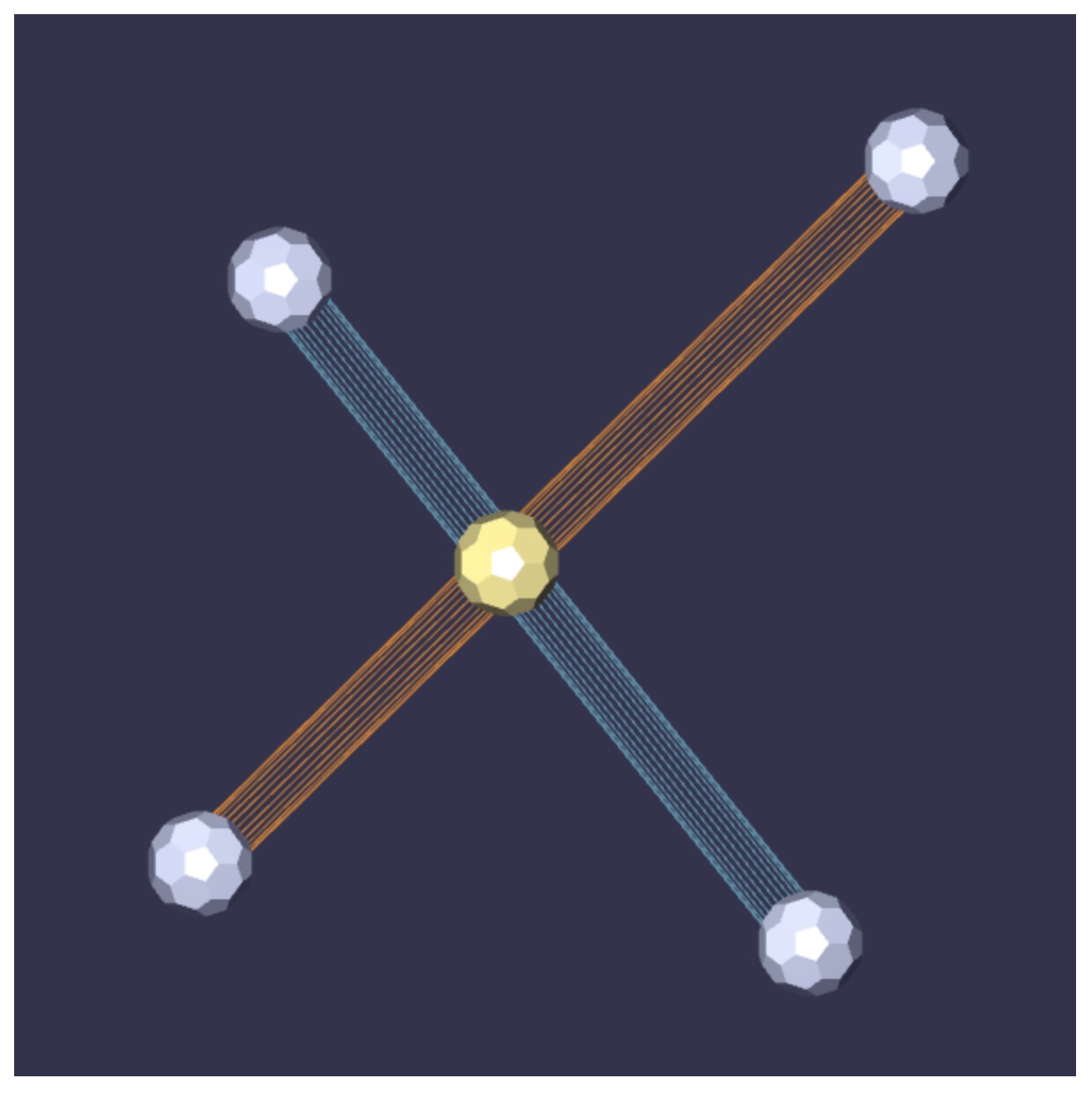
I’ve included two other WebGL applications that are run by loading the HTML files segment-intersect.html and facet-hit.html. The first of these is shown below, and can be used to test your 2-D line segment intersection code. When loaded, the application shows two line segments embedded in the plane. Their endpoints can be clicked on and dragged around. The application also displays an intersection point, as computed by segmentsIntersect within walk-thru-library.js. You can see that code working correctly in the sample image below. Instead, if you have not re-written this intersection code yet, the application will just show the midpoint of the blue segment P0P1P0P1.
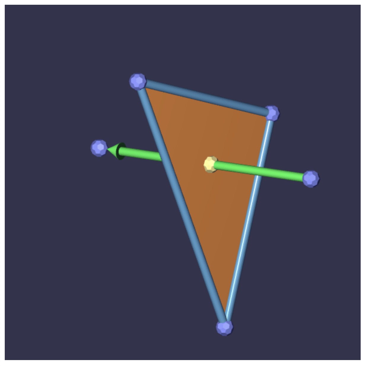
The second application is shown below. When loaded, it shows a triangular facet in 3-space along with a ray that passes from one point to another. The viewpoint of this scene can be re-oriented by clicking and dragging the scene with the mouse, either while pressing down on the SHIFT key or by using the middle button of the mouse. And then each of the five control points can be selected and dragged around so as to vary the set-up. The application will display an intersection point as returned by rayFacetIntersect within walk-thru-library.js. You can see that code working correctly in the sample image below. If you haven’t written that intersection code yet, the application will just show the barycenter of the triangular facet given by Q1Q2Q3Q1Q2Q3.
Alias/Wavefront .OBJ files
The HTML file contains a section with the text of several Alias/Wavefront .OBJ files. These each describe the vertices and faces of each of the scene objects in the object library. Here, for example, is the description of the hinged pair of squares used in some of the example images. They can be placed using the squares button.
v -1.0 0.2 -1.0
v 0.1 -1.0 -1.0
v 1.0 0.1 -1.0
v 0.05 1.0 -1.0
v -2.0 0.1 -3.2
v 0.1 -2.0 -3.2
v 2.0 0.1 -3.2
v 0.2 2.0 -3.2
f 1 2 4
f 4 2 3
f 5 6 8
f 8 6 7
Each file contains, minimally, a list of all the vertex locations for an object on lines starting with v. There are 8 verices, one for each hinge. And then these are followed by the description of each face on lines starting with f. The first face connects the vertex on the first ine, with the one on the second, with the one on the fourth line, forming a triangle. And then also this means that the surface has the three edges 1->2, 2->4, and 4->1.
As noted in the bells and whistles, lots of these files can be found, although often these are ones obtained by some high-resolution 3-D scanner, and so they have lots of vertices and lots of facets.
The files can contain other information. Some of our objects have vertex normals specified. This allows renderers to perform smooth shading of the surface by interpolating the vertex normals along the points of a face using some lighting and shading models like we learned in class. Vertex normals start with the line vn. Similarly vertex texture coordinates can be specified, as well. These allow a renderer to wrap an image as the detailing of a face. Vertex texture coordinates are specified with vt lines.
These two additional pieces of information can show up in the descriptions. Our lower resolution teapot.obj has the face line f 22/10/22 1/13/1 4/14/4 23/11/23 which directs a renderer to make a five-sided face with vertices from lines 22, 1, 4, and 23. But then the othersnumbers indicate each vertex’s vt and vn line.
Our processing of the files ignores these extra bits of information.
Feel free to add or create your own objects by adding them to the HTML. A warning: they shouldn’t have too many facets. The code we are writing uses a lot of Javascript calculations to create the PDF, so only use objects with low triangle counts.
Object specification
Object library
The HTML file has a section of buttons that allow the user to specify what object gets cloned when placing scene objects. These requests are sent to the editor by a string like "cube" or "teapot". These serve as keys to a Map that serves as a dictionary of object descriptions. More specifically, each entry in the object library maps the object name to the processed contents of a .OBJ file.
The libary is built upon startup of the editor, Each object gets compiled so that glBeginEnd calls can be issued to render them where they are each placed. There is a GL_TRIANGLES call for the flat-shaded object to be drawn as part of the walk-through scene. And also there is a GL_LINES call for rendering the mesh wireframe of the object.
Object representation
We represent each object in the library as a CGObject instance, and this class is defined in the source cg-object.js. These objects contain a surface mesh data structure compiled from the information in a .OBJ file. Each object has an array of vertices, an array of faces, and an array of edges that serve as the boundaries of faces.
Relevant to this project, every edge knows its two vertices, and every face knows its three vertices. And, it turns out, each edge knows the face(s) it borders. This could be a single face, if that edge serves as the boundary of a face. Or it could be two faces, if that edge serves as a hinge between two faces. The fact that edges, vertices, and faces relate to each other give the topological structure of the surface, essentially providing a means to walk around its edges and its faces.
Step 4 above talks about ray casting to determine whether a portion of an edge that gets drawn. We pointed out that your code might need to exclude the one/two faces of an edge so that it is/they don’t hide their own edge. If you have access to an edge object e, then you can access a short array of its faces with e.faces().
The fact that each edge can be shared by two faces adds a little complexity to the representation. In processing the .OBJ file, we make sure we don’t add the same geometric edge twice. This means that, instead, when an edge forms the hinge between two triangles, only one Edge object instance is made.
Scene objects
There is a separate representation class for objects that need to be rendered. In walk-thru.js we describe a Placement of a CGObject, giving its library name, its position, its scale, and its orientation. When the time comes to render a scene into PDF, each object placement is converted into several “clones” of their CGObject data.
We represent the geometry of a cloned library object with a class named SceneObject. This is a subclass of CGObject, but with additional support for projecting and rendering the object as lines in the PDF. It actually shares the topological information (the edge and face structure) with its CGObject from which it was cloned. It refers to these same edge and vertex sets from its “parent”, but then has a different set of vertex objects, in different locations, then its parent library object.
The fact that clones share face and edge information with their parent complicates access to vertex information. When asking for a edge’s endpoints, you need to specify the object so you get the relevant vertex object. The same edge on the clone and its parent must lead to different vertex objects for the edge endpoints, depending on hen you are dealing with the parent or with the clone.
Below are the most needed and relevant calls in the code for obtaining information from a scene object so that you can render it in PDF:
vs = so.allEdges();     // Get the edges of a SceneObject
fs = so.allFaces()      // Get the faces of a SceneObject
vs = so.allVertices()   // Get the vertices of a SceneObject

v = f.vertex(i,so)  // Look up the vertices of a face wrt `so`
v = e.vertex(i,so)  // Look up the vertices of an edge wrt `so`

e.faces()   // Get the one/two faces of an edge.
v.position  // Get the `Point3d` location of a vertex.
PDF file support
The code we write for creating PDF documents is from a freely available library called jsPDF. This API is one of several. It is well-documented and has many nice demonstrations and examples at links from its GitHub repo.
Beyond lines and dots, you can lay out text in different fonts, and at slants. You can make filled regions. You can lay out curves, and so on. Our code makes a credit card-sized PDF and we use millimeters as the unit for placing lines and dots. There is of course support for other document sizes and other drawing units, as well.
I recommend checking it out.