

Description
CSCE 441 Assignment 1 Rasterizer
Goal
Create a program that reads in and renders a triangle mesh (of type .obj) to an image via software rasterization. You may use existing resources to load in the mesh and to write out an image. You must write your own rasterizer. In general the required steps for the program are:
- Read in triangles.
- Compute colors per vertex.
- Convert triangles to image coordinates.
- Rasterize each triangle using barycentric coordinates for linear interpolations and in-triangle test.
- Write interpolated color values per pixel using a z-buffer test to resolve depth.
Associated Labs
- Lab -1 (required): Setting Up Your Development Environment. For A1, only the compiler and CMake are required, so only Lab Negative One is required, not Lab Zero.
- Lab 1 (optional): Bounding Box Rasterizer. See this lab if you need an example of how the
Imageclass is used. - Lab 2 (optional): Single Triangle Rasterizer.
Setting Up Your Code
Download the Assignment 1 base code, which has a mesh loader and an image writer. Compile and run the code by following the same set of commands as in Lab -1.
The mesh loader is an obj loader from https://github.com/syoyo/tinyobjloader, and the image writer is from https://github.com/nothings/stb.
When the mesh is loaded, the vertex positions are stored in the posBuf array as follows:
-----------------------------------------------------------------------------------------------
| x0 | y0 | z0 | x1 | y1 | z1 | x2 | y2 | z2 | x3 | y3 | z3 | x4 | y4 | z4 | x5 | y5 | z5 | ... <- posBuf array
-----------------------------------------------------------------------------------------------

|   vertex 0   |   vertex 1   |   vertex 2   |   vertex 3   |   vertex 4   |   vertex 5   |
|                 triangle 1                 |                 triangle 2                 |
Every three consecutive vertices in this array forms a triangle. In other words, every nine elements form the (x,y,z) coordinates of the three vertices of a triangle. (For now you can ignore the normal and the texture coords.) Example mesh files are included in the base code. In addition, there are numerous OBJ meshes on the web. For grading purposes, your program will be run using the provided Stanford Bunny and Utah Teapot.
Ultimately you will want each triangle to be represented in a C/C++ structure/class, with 3 vertices and a color per vertex. In addition, your triangle data should include a 2D bounding box, which will represent the triangle’s extents in image coordinates.
Add a command line argument to accept the following command line arguments.
- Input filename of the .obj file to rasterize
- Output image filename (should be png)
- Image width
- Image height
- Task number (1 through 7)
For example, your program should be able to be run as follows:
> ./A1 ../resources/bunny.obj output.png 512 512 1(In Xcode, the 1st argument should be ../../resources/bunny.obj.) Add error checking to specify the required command line arguments if an incorrect number are given. Your program should not dump core if no input file is specified, or fail without an error message! Follow the golden rule; treat your user/grader/instructor the way you’d like to be treated as a user/grader/instructor.
Task 1: Drawing Bounding Boxes
Write code to convert each 3D coordinates into 2D image coordinates. Assume the camera is at the origin looking down the negative z axis. Make sure the object completely fills the image without any distortion. To do so, you need to compute the scale and translation factors as we discussed in class. Some tips for starting out:
- You’ll need a bounding box for the whole mesh as well as for each triangle.
- Color each triangle with the colors defined in
RANDOM_COLORS. For theith triangle, the color should beRANDOM_COLORS[i%7]. - Start with
tri.obj, which contains a single triangle.
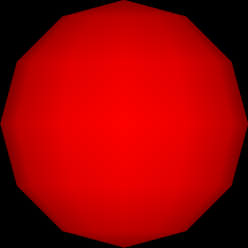
First, write out the bounding box, rather than the triangles, to the image. If you do this with the provided tri.obj, sphere.obj, teapot.obj, and bunny.obj, you should see blocky images like below. The 0th triangle should use RANDOM_COLORS[0], the 1st triangle should use RANDOM_COLORS[1], etc.


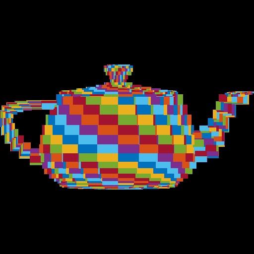
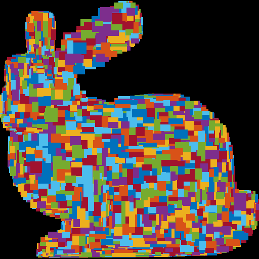
The object must take up the whole image, be centered, and be undistorted (not stretched). Make sure you test nonuniform window sizes. As shown below, the aspect ratio of the object should be preserved no matter what the image size is, and the object should fill out the image.


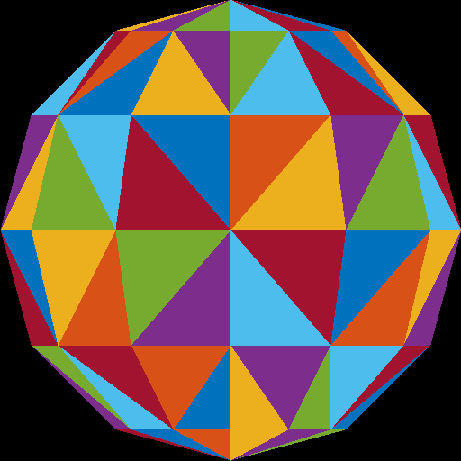
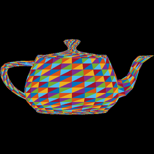
Task 2: Drawing Triangles
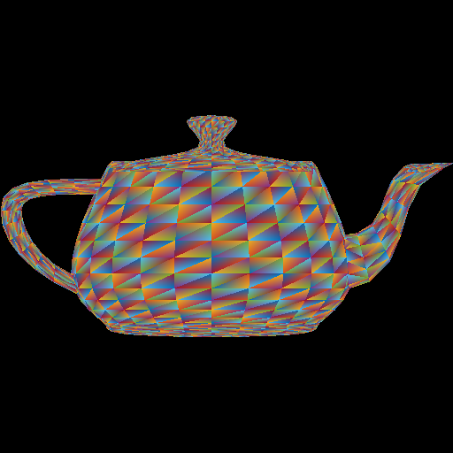
Once the bounding boxes are being displayed correctly, add the barycentric test to write out the triangles as in (optional) Lab 2. This should be the output when the “task” command line argument is set to 2. You should not see any gaps between the triangles.


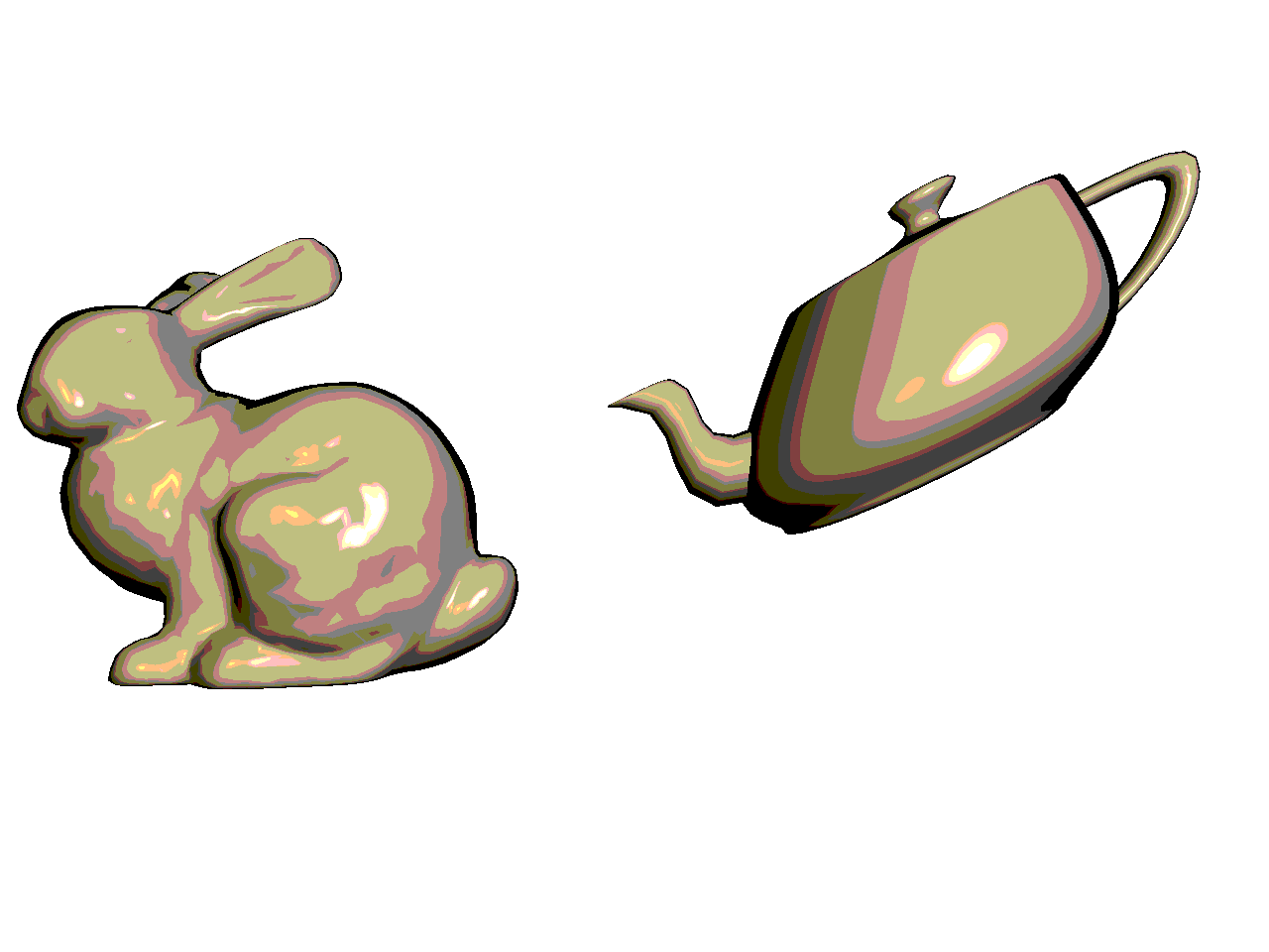
Here is another image of a bunny and a teapot, from Alice in Wonderland [Wikimedia].

Task 3: Interpolating Per-Vertex Colors
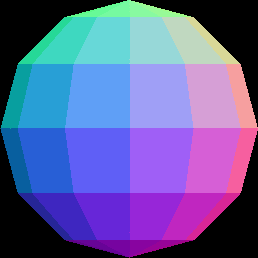
Instead of using random per-triangle colors, use random per-vertex colors. For each pixel inside each triangle, you need to interpolate the pixel’s color from the three vertices using the pixel’s barycentric coordinates.

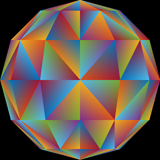
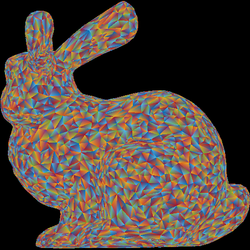
Optional information: Because of the way we are loading the mesh, the triangles do not share any vertices. For example, if we were to load a square consisting of four vertices and two triangles, we end up with six vertices – three for each of the triangles. In other words, we end up duplicating any shared vertices. Therefore, when we assign a color to each vertex, triangles having a vertex at a common position can have different colors assigned at this vertex position. For example, in the sphere image above, the center vertex is incident to eight triangles, and so it has been duplicated eight times, each time with a different random color. For further information check out indexed drawing.
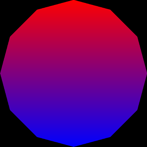
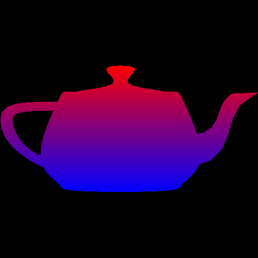
Task 4: Vertical Color
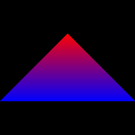
Next, use the y-value to linearly interpolate two colors: blue (0 0 255) and red (255 0 0). The color should vary smoothly from top of the object to the bottom of the object, rather than from the top of the whole image to the bottom of the whole image. In other words, the top tip of the triangle should be fully red.

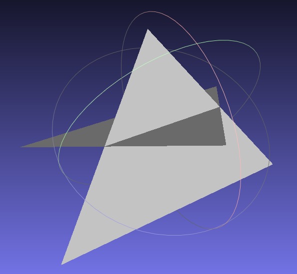
Task 5: Z-Buffering
Now that you have interpolated colors, implement z-buffer tests. First, create a data structure to support z-buffer tests. Your z-buffer should be a separate buffer from your image pixel buffer, and it should be the same size as your pixel buffer. The z-buffer contains the z-coordinate of each pixel, which is interpolated from the z-coordinates of the three vertices using the pixel’s barycentric coordinates. Once you have z-buffer implemented, you should be able to render tri2.obj properly – the two triangles should be intersecting. In the right image below, the triangles are rendered with per-vertex colors.

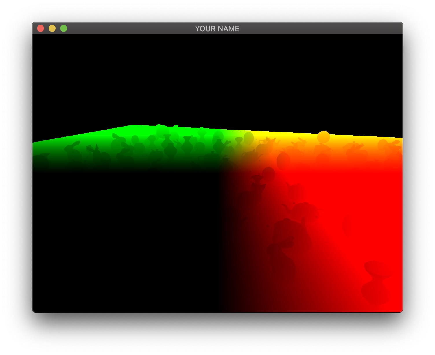
Now, use the z value of the pixel as the red color (use 0 for both blue and green). To do this, you have to map the z-value to the range 0 to 255. If your z-buffer test is not working, you’ll see some strange results, since some pixels that are farther from the camera may be drawn on top of closer pixels.

If your z-buffer is working, and if you’re interpolating the colors correctly, you should get the following results for the four obj files.


Important Note
Make sure to pass your std::vector by reference rather than by value. (E.g., void foo(std::vector<float> &bar)) Otherwise, your program may become too slow. Since the Image class has an std::vector inside it, it should also be passed by reference.
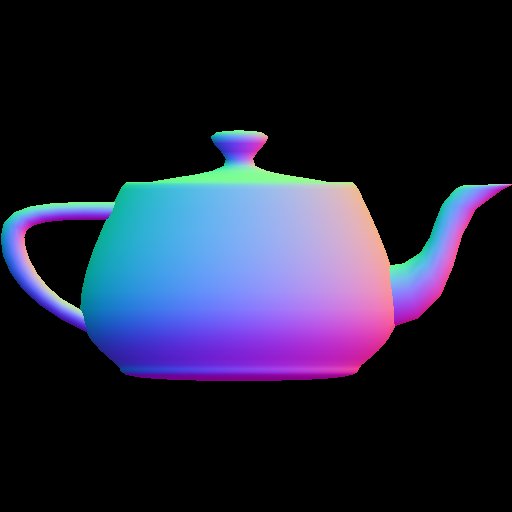
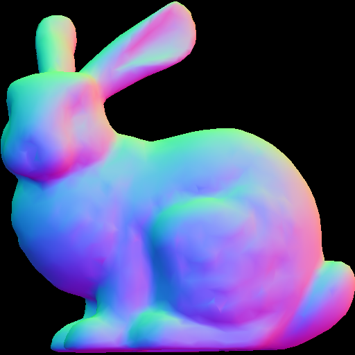
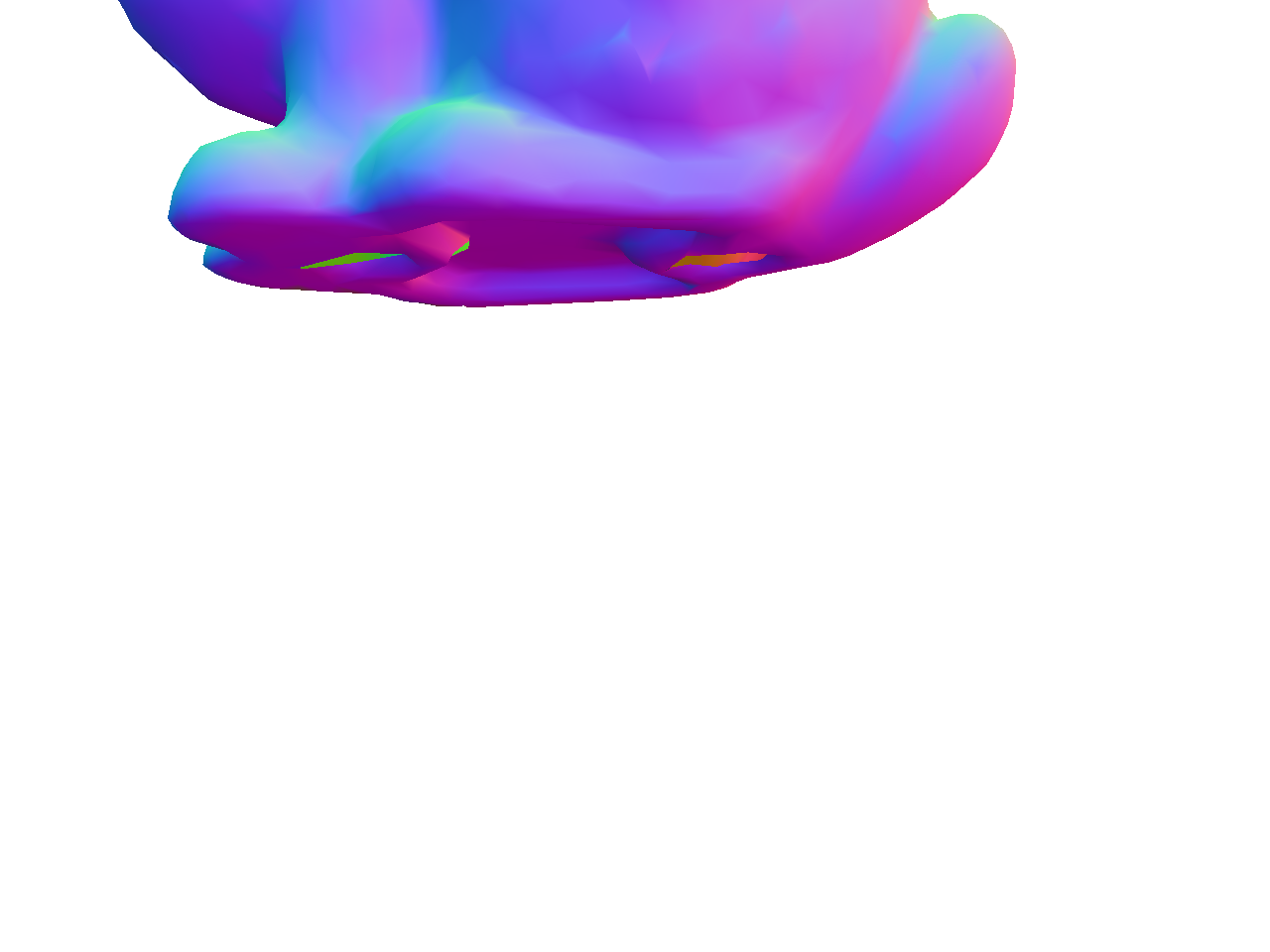
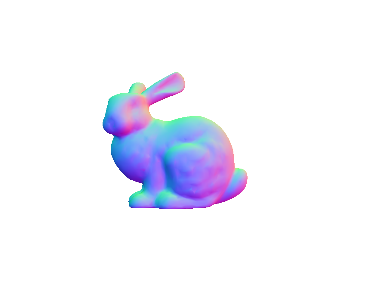
Task 6: Normal Coloring
When we load the obj file, we are also loading the vertex “normals” of the mesh, in addition to the vertex positions. These are stored in the norBuf variable alongside the posBuf variable that are already being used. Store this “normal” information (a 3D vector) in each vertex. Then, when coloring the pixels, interpolate the normals of the three vertices of the triangle to compute the normal of the pixel.
A normal is a 3D direction, so its (x,y,z) values can be anything in the range [−1,1]. To display the normal as a color, we need to map these values to the range [0,255]. The expression for this mapping is
r = 255 * (0.5 * x + 0.5);
g = 255 * (0.5 * y + 0.5);
b = 255 * (0.5 * z + 0.5);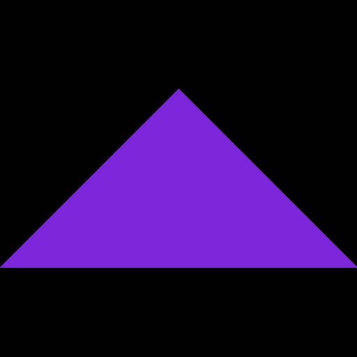
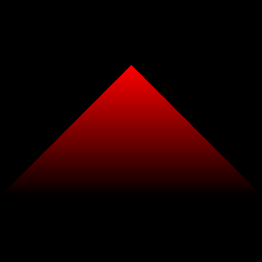
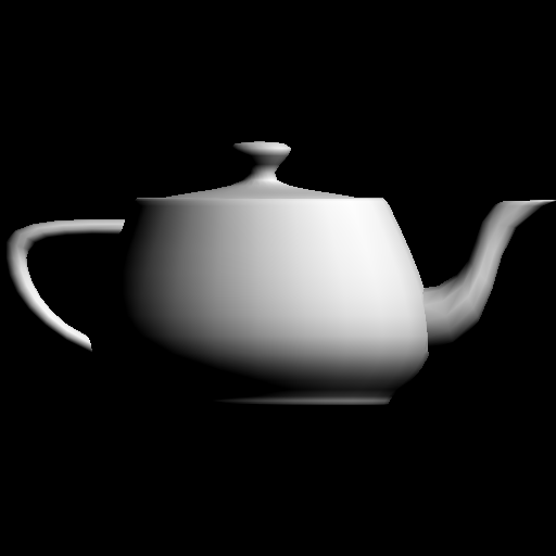
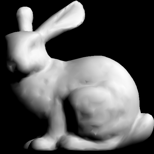
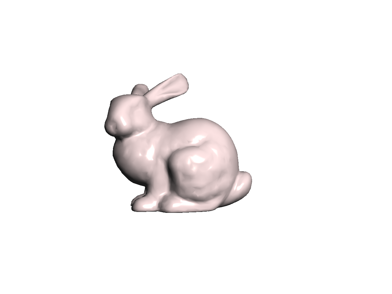
Task 7: Simple Lighting
Finally, apply simple “lighting” calculation to compute the color of each pixel. After the normal �^ has been computed at a pixel, compute the following:
�=max(�^⋅�^,0),�^=13(111).
The “light” vector �^ is the 3D direction of the light. Take the dot product between the normal and the light vector, and take the maximum of the result and zero. Without this zero, pixels that are facing away from the light will also be lit, which is not what we want. The resulting scalar, �, should be applied to RGB equally:
�=�,�=�,�=�.
Note that with the single triangle scene, we get an empty image because the triangle is facing away from the light.


Point breakdown
- 10 points for Task 1 with a square image
- 10 points for Task 1 with a rectangular image
- 10 points for Task 2 (Triangle)
- 10 points for Task 3 (Per-vertex)
- 10 points for Task 4 (Vertical)
- 20 points for Task 5 (Z-Buffering)
- 10 points for Task 6 (Normal)
- 10 points for Task 7 (Lighting)
- 10 points for coding style and general execution. For example, do not put everything in
main(), and remember to pass big data by reference.
Total: 100 points
What to hand in
Failing to follow these points may decrease your “general execution” score.
On Linux/Mac, make sure that your code compiles and runs by typing:
> mkdir build
> cd build
> cmake ..
> make
> ./A1 <ARGUMENTS>
If you’re on Windows, make sure that you can build your code using the same procedure as in Lab -1.
- Make sure the arguments are exactly as specified.
- Include an README file (ascii only) that includes:
- Your name, UID, and email
- The highest task you’ve completed
- Citations for any downloaded code (e.g., barycentric)
- Plus anything else of note
- Remove unnecessary debug printouts.
- Remove unnecessary debug code that has been commented out.
- Hand in
src/,resources/,CMakeLists.txt, and your README file. - Do not hand in:
- The build directory
- The executable
- Old save files
(*.~) - Object files
(*.o) - Visual Studio files
(.vs) - Git folder
(.git)
- Create a single zip file of all the required files.
- The filename of this zip file should be
UIN.zip(e.g.,12345678.zip). - The zip file should extract a single top-level folder named
UIN/(e.g.12345678/). - This top-level folder should contain your README,
src/,CMakeLists.txt, etc. - Use the standard
.zipformat (not.gz,.7z,.rar, etc.).
- The filename of this zip file should be
CSCE441 Assignment 2 – Hierarchical Transforms
Goal
Learn and apply hierarchical 3D transformations using the matrix stack.
Associated Labs
- Lab 0 (required): Setting Up Your Development Environment
- Lab 3 (optional, tedious!): Transformation Matrices
- Lab 4 (recommended): Matrix Stack
Overview
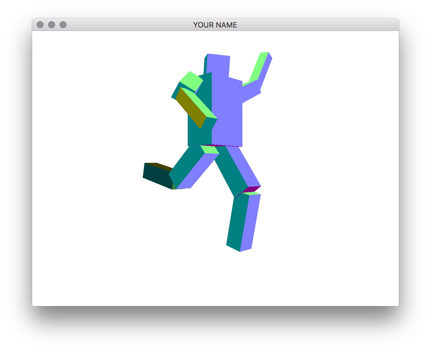
Write a program that allows you to create a robot that you can manipulate with the keyboard. You are free to create your own robotic character, but there should be at least 10 components in the robot, and the hierarchy should not be flat. For example, in the figures below, we have the following hierarchy:
- Torso
- Head
- Upper left arm
- Lower left arm
- Upper right arm
- Lower right arm
- Upper left leg
- Lower left leg
- Upper right leg
- Lower right leg
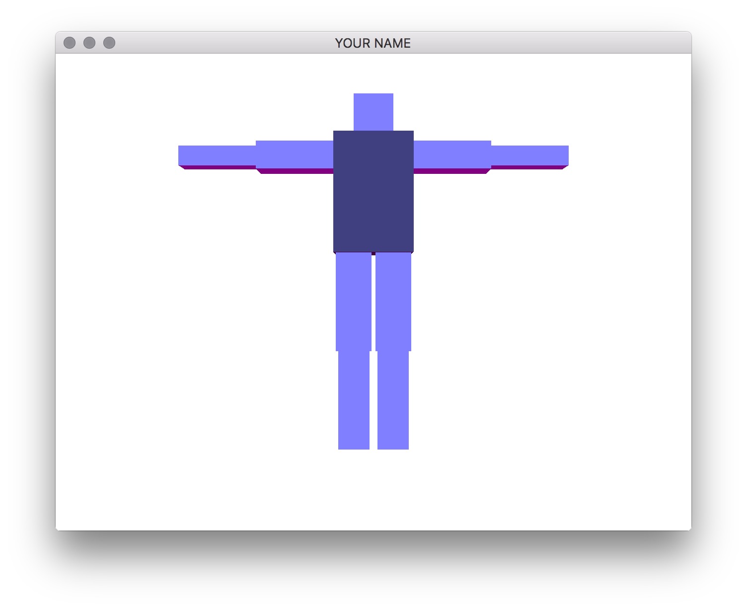
The exact size, placement, and rotation of these components are up to you. These hard-coded values should be used in the init() function, not the render() function.
Task 1
Start from your Lab 0 or Lab 4 code base.
- Create your
A2project folder and copy the the lab files and folders into it. - Modify
CMakeLists.txtto change the project name (line 4). - Add GLM calls so that you can draw transformed squares. There are two choices:
- If you’re starting with Lab 4, then you should already have this done.
- If you’re starting with Lab 0, then replace the teapot with a cube and then try transforming it.
- The benefit of starting with Lab 0 is that it contains the helper classes (e.g.,
Shape,Program, etc.) to help you organize your code. You will be required to do this for later assignments.
- The benefit of starting with Lab 0 is that it contains the helper classes (e.g.,
- Add support for keyboard input (x/X, y/Y, z/Z) by using the
glfwSetCharCallback()function.
Task 2 (optional)
You may skip ahead to Step 3 if you understand how to draw the components recursively. In this step, we are going to draw just the torso and the head without recursion so that you first understand how the transforms chain together.
In your render() function, first draw the torso and the head without any hierarchy:
prog->bind();
glUniformMatrix4fv(prog->getUniform("P"), 1, GL_FALSE, value_ptr(P));
// Draw the torso
MV->pushMatrix();
    MV->translate(...); // Where is the torso with respect to the world?
    MV->rotate(...); // This rotation applies only to the torso
    MV->scale(...); // This scale applies only to the torso
    glUniformMatrix4fv(prog->getUniform("MV"), 1, GL_FALSE, value_ptr(MV));
    shape->draw(prog);
MV->popMatrix();
// Draw the head
MV->pushMatrix();
    MV->translate(...); // Where is the head with respect to the world?
    MV->rotate(...); // This rotation applies only to the head
    MV->scale(...); // This scale applies only to the head
    glUniformMatrix4fv(prog->getUniform("MV"), 1, GL_FALSE, value_ptr(MV));
    shape->draw(prog);
MV->popMatrix();
prog->unbind();
Note: In this pseudocode, I’m assuming that P and MV are matrices. In your code, these may instead be pointers to MatrixStack, in which case you need to call glm::value_ptr(P->topMatrix()). (Don’t forget #include <glm/gtc/type_ptr.hpp>.) Alternatively, you can write &P->topMatrix()[0][0].
The indentation between push and pop helps with clarity but is not necessary. The first call to glUniformMatrix4fv() sends the projection matrix to the GPU. Then, we modify the modelview matrix, send it to the GPU, and then draw the shape. With this naive version, changing the position or the rotation of the torso does not modify the head.
To fix this, we now add some pushes and pops. Note that when we rotate the torso, we want the head to also rotate, but when we change the scale of the torso, we do not want to change the scale of the head. Therefore, we use an extra push/pop around the torso scale:
...
// Draw torso
MV->pushMatrix();
    MV->translate(...); // Where is the torso's joint with respect to the world?
    MV->rotate(...); // This rotation applies to torso and its children
    MV->pushMatrix();
        MV->translate(0, 0, 0) // Where is the torso's mesh with respect to the torso's joint?
        MV->scale(...);
        glUniformMatrix4fv(prog->getUniform("MV"), 1, GL_FALSE, value_ptr(MV));
        shape->draw(prog);
    MV->popMatrix();
    // Draw head
    MV->pushMatrix();
        MV->translate(...); // Where is the head's joint with respect to the torso's joint?
        MV->rotate(...); // This rotation applies to head and its children
        MV->pushMatrix();
            MV->translate(...) // Where is the head's mesh with respect to the head's joint?
            MV->scale(...);
            glUniformMatrix4fv(prog->getUniform("MV"), 1, GL_FALSE, value_ptr(MV));
            shape->draw(prog);
        MV->popMatrix();
    MV->popMatrix();
MV->popMatrix();
...
With the code above, translating and rotating the torso should also translate and rotate the head. Note that with this hierarchical version, the numbers used for translation/rotation/scale of the head may be different than with the previous non-hierarchical version, since now we are defining the head with respect to the torso.
Task 3
Now we are going to create a general, hierarchical structure for drawing a robot with multiple limbs.
Create a class that represents a component. This class should contain the necessary member variables so that you can make a tree data structure out of these components. The root of the tree should represent the torso, which means that transforming the torso transforms everything else.
In addition to the member variables required for the tree hierarchy, the class should also have the following:
- A
glm::vec3representing the translation of the component’s joint with respect to the parent component’s joint. - A
glm::vec3representing the current joint angles about the X, Y, and Z axes of the component’s joint. (You may want to start with Z-rotations only.) - A
glm::vec3representing the translation of the component’s mesh with respect to its joint. - A
glm::vec3representing the X, Y, and Z scaling factors for the mesh. - A member method for drawing itself and its children.
- Any additional variable(s) and method(s) you see fit.
The drawing code should be recursive – in other words, in the render() function in main.cpp, there should be a single draw call on the root component, and all the other components should be drawn recursively from the root. In the main render() function, you should create an instance of the matrix stack class and pass it to the root component’s drawing function. Make sure to pass the matrix stack by reference or as a (smart) pointer.
The component’s rendering method should simply take the current state of the component and draw it. You should not create the robot hierarchy in this method. In other words, the scene setup must be done in main’s init() rather than in main’s render(). In your README, state where in your init() function (which line) should be modified to change the joint angles.
For this assignment, the 3D rotation of the joint should be represented simply as a concatenation of three separate rotation matrices about the x-, y-, and z-axes: Rx * Ry * Rz. The position of the joint should not be at the center of the box. For example, the elbow joint should be positioned between the upper and lower arms.
Task 4
Add the functionality to select components and rotate the joints with the keyboard. When the appropriate key is pressed, the currently selected component, along with all of its descendants, should be rotated about the joint. For example, if the upper right arm is rotated, the lower right arm should rotate with it. The keyboard control should be as follows:
.(period): traverse the hierarchy forward,(comma): traverse the hierarchy backwardx/X: increment/decrement x angley/Y: increment/decrement y anglez/Z: increment/decrement z angle
By pressing the period and comma keys, you should be able to select different components in the hierarchy. You must draw the selected component so that it is distinguishable from unselected components. The x/X, y/Y, and z/Z keys should change the rotation angle of the selected component. In the left figure above, the torso is the selected component, and in the right figure, one of the lower legs is the selected component.
The traversal of the tree with the period and comma keys should be in depth-first or breadth-first order. Do not hardcode this traversal order – your code should be set up so that it works with any tree.
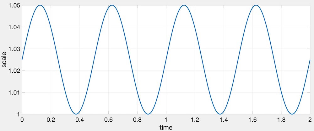
When drawing the selected component, change its size using the time variable. In the render() function, use the following GLFW call:
double t = glfwGetTime();This t variable should then be used to change the scale as follows:
�(�)=1+�2+�2sin(2���),
where � is the amplitude, � is the frequency, � is the time, and � is the resulting scale. The following values work well: �=0.05, and �=2. In other words, the scale increases by 5% twice a second. Here is a plot of this function.
Here is a working example:
Task 5
Put a cube at each joint. The cube should be placed exactly where the joint is, so that when the joint is rotated, the cube does not translate. These cubes should not be in the hierarchy. Instead, they are simply extra things to be drawn while traversing the hierarchy.
For bonus, instead of drawing a cube, draw a sphere.
Task 6
Rotate at least two components in place. This rotation should not be propagated to its children. At least one of the two should be a non-leaf component.
HINT: Debugging OpenGL & GLSL
- Set the Program class to be verbose by calling the
setVerbose()function. If there is a GLSL compilation error, then you will see the error in the console. For example, if the varying variables of the vertex shader and the fragment shaders do not match up, it will tell you so. Make sure to set verbose to be false after debugging. - Use
GLSL::checkError(GET_FILE_LINE);to find which OpenGL call caused an error. This function will assert if there were any OpenGL errors before getting to this line. You can use this to winnow down which OpenGL function is causing an error. For example, if you put this line at the top, the middle, and the bottom of your function, and if the assertion happens in the middle, you know that the error must be happening in the top half of your function. Once find exactly which OpenGL call is causing the error, you can Google the OpenGL function to figure out what caused the error. For example, maybe one of the arguments should not have been zero or null. - The GLSL compiler will silently optimize away any variables that are not used in the shader. If you try to access these variables at runtime, the program will crash, since these variables no longer exist in the shader. In this lab, when you move the computation of the normal to the GPU, the
aNorvariable no longer needs to be passed to the GPU, since it is computed in the shader. Therefore, you will have to comment out any reference toaNorfrom your C++ runtime code. Or, you can trick the GLSL compiler from optimizing awayaNorby using it and disgarding it as follows:vec3 nor = aNor.xyz; nor.x = ...; nor.y = ...; nor.z = ...;
Point breakdown
Task 2 is optional. If you have completed Task 3, you will get full points for Task 2.
- 10 points for Task 2a: drawing the torso and head without hierarchy.
- Specify in the README where (which line in the code) to change the rotation angles.
- 15 points for Task 2b: drawing the torso and head with hierarchy.
- Specify in the README where (which line in the code) to change the rotation angles.
- 20 points for Task 3: a functioning hierarchical robot with hard coded angles.
- Specify in the README where (which line in the code) to change the rotation angles.
- 20 points for Task 4: being able to select different components with the keyboard and for showing the current selection with a different size.
- Once this task is implemented, you can remove the note in the README where you specify where to change the joint angles.
- 15 points for Task 5: cubes at the joints.
- 15 points for Task 6: for animation.
- 5 points for coding style and general execution.
- Must use recursive, object-oriented design.
- Hard-coded values must be set in
init(), notrender().
- 5 bonus points for drawing spheres at the joints.
Total: 100 + 5 points
What to hand in
Failing to follow these points may decrease your “general execution” score. On Linux/Mac, make sure that your code compiles and runs by typing:
> mkdir build
> cd build
> cmake ..
> make
> ./A2 ../resources
If you’re on Windows, make sure that you can build your code using the same procedure as in Lab 0.
- Make sure the arguments are exactly as specified.
- Include a README file (ascii only) that includes:
- Your name, UID, and email
- The highest task you’ve completed
- Citations for any downloaded code
- Plus anything else of note
- Remove unnecessary debug printouts.
- Remove unnecessary debug code that has been commented out.
- Hand in
src/,resources/,CMakeLists.txt, and your readme file. The resources folder should contain the obj files and the glsl files. - Do not hand in:
- The build directory
- The executable
- Old save files
(*.~) - Object files
(*.o) - Visual Studio files
(.vs) - Git folder
(.git)
- Create a single zip file of all the required files.
- The filename of this zip file should be
UIN.zip(e.g.,12345678.zip). - The zip file should extract a single top-level folder named
UIN/(e.g.12345678/). - This top-level folder should contain your README,
src/,CMakeLists.txt, etc. - Use the standard
.zipformat (not.gz,.7z,.rar, etc.).
- The filename of this zip file should be
CSCE441 Assignment 3 – Shaders
Goal
Integrate the various concepts learned in the lectures and create a program that can color the mesh with various materials, lights, and shaders.
Associated Labs
- Lab 0 (required): Setting Up Your Development Environment
- Lab 5 (optional): Introduction to OpenGL & GLSL
- Lab 6 (optional): Further Introduction to OpenGL & GLSL
- Lab 7 (recommended): Phong Fragment Shading. Make sure you can get the cube to render exactly as shown in the lab.
Task 1: Centering the Bunny
Start with the skeleton code. The input argument should be the path to the resources folder, exactly as in Lab 0. Optionally, there is an argument that sets the OFFLINE flag to true, in which case the program will save the first OpenGL screen as an image file and then exit. We will be using this to help speed up the grading process, so do not modify the way arguments are parsed.
The initial scene draws a single bunny. The only transform applied is the viewing transform, implemented in the Camera class. The initial camera position is at (0, 0, -2), and the mouse applies a turn-table style rotation about the world origin. Try dragging the mouse around to rotate the bunny.
Transform the bunny so that it is scaled by 0.5 and is translated by (0.0f, -0.5f, 0.0f). The resulting bunny should appear near the center of the window. Note the right ear of the bunny. If it looks different from the image, try swapping the order of translation and rotation.
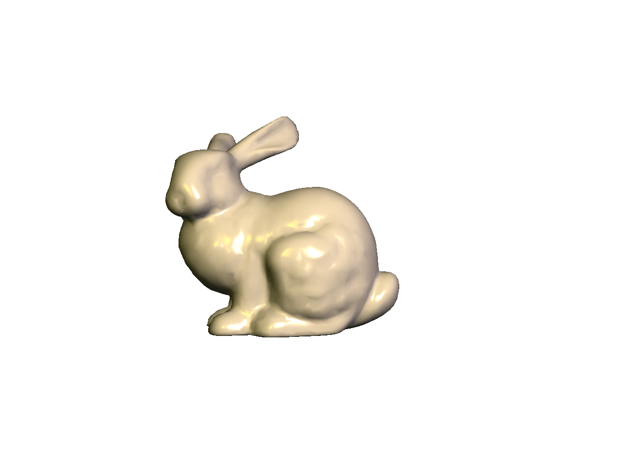
Task 2: Blinn-Phong Shading
Next we’re going to add a Blinn-Phong shader. (Look at Lab 7.) Set up the code so that pressing the s/S keys cycles through the two shaders (Normal and Blinn-Phong). As we add more shaders in the subsequent tasks, the s/S keys will be used to cycle through more and more shaders.
Create three materials and add keyboard hooks to cycle through them using the m/M keys. You should create a Material class for this. (After you create new files (cpp/h), you have to rerun cmake. You don’t need to delete your build folder to do this.) The three materials should look like the following.
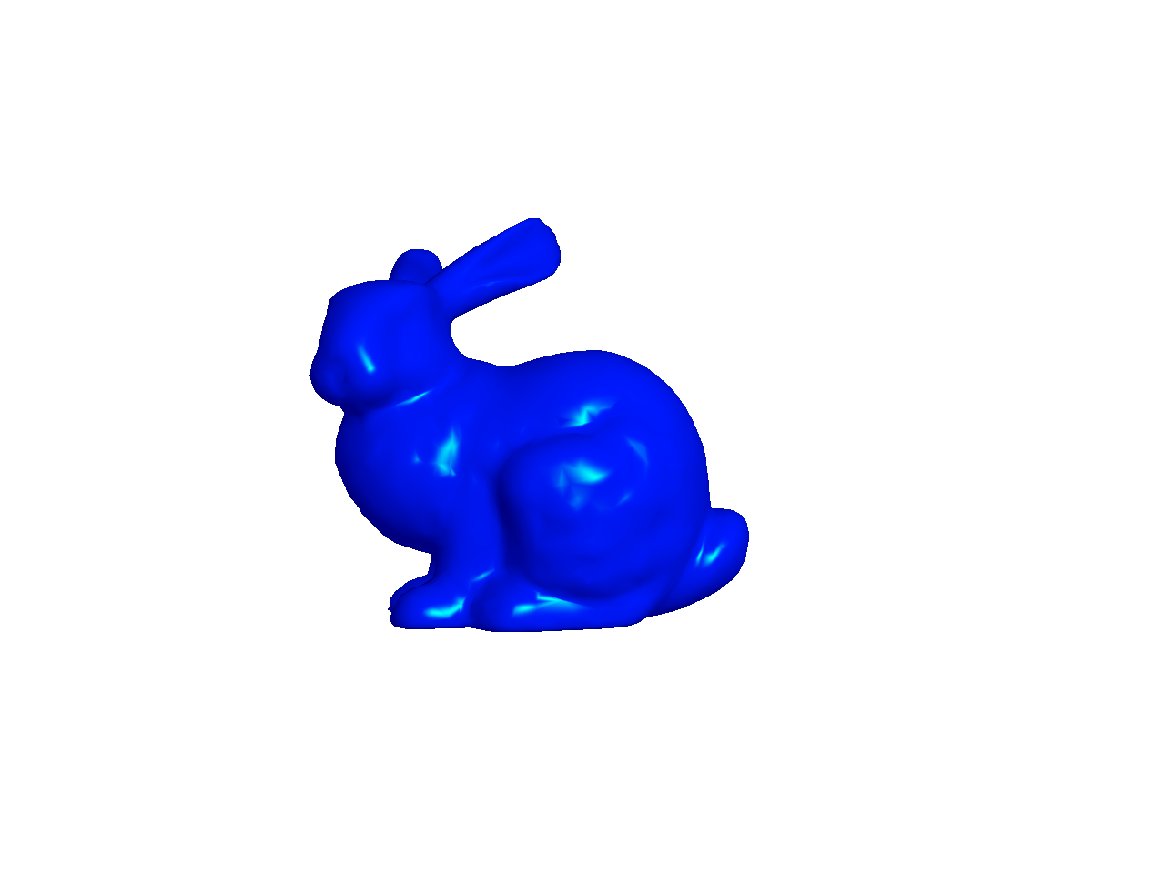
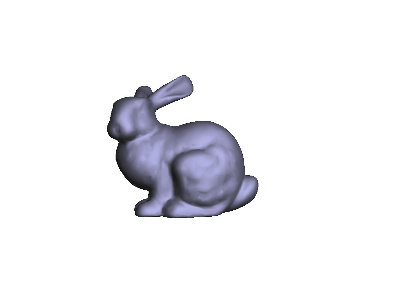
In these examples, the light color should be white, and the light position should be (1, 1, 1) in camera space.
- The first material should be pinkish with very strong highlights.
- The second material should be blue with green highlights.
- The third material should be grayish with low shininess.
The parameters for the first material must be exactly the same as in Lab 7:
- ��: (0.2,0.2,0.2)
- ��: (0.8,0.7,0.7)
- ��: (1.0,0.9,0.8)
- �: 200
For the second and third materials, you will have to try some values to get the desired effect. Feel free to message us on Canvas to check if your results are acceptable.
Make sure to use the inverse transpose of the modelview matrix to transform the normal. The inverse transpose matrix should be calculated in your C++ code and passed in as a uniform mat4 to the vertex shader. (Look at the GLM docs for inverse() and transpose().) After transforming the normal with the inverse transpose modelview matrix, the resulting normal should be normalized and then passed to the fragment shader. The interpolated normal in the fragment shader should be normalized again. Note that this was optional in Lab 7, because the modelview matrix only consisted translations and rotations. In this task, we have a scale, and then in a later task, we will include a shear.
As in Lab 7, we’re not going to do attenuation in this assignment.
Multiple Shaders
Note that you should not use an if/switch statement in the vertex/fragment shader to toggle between the Normal and Blinn-Phong shaders. Even though this works fine, it is not the right way to do things. First, it adds an extra conditional in the fragment shader, which is executed for every single vertex or fragment, which is bad from an efficiency point of view. Second, this may work for a simple assignment, but in a bigger project with multiple objects, this will get ugly quickly. The proper way is to put the if/switch inside the CPP file. You should do something like this:
if(something) {
    glUseProgram(pid0);
} else {
    glUseProgram(pid1);
}
Of course, there are other ways to do this as well. The important thing is to not have the if/switch statement in your shaders for toggling between programs. We want the shaders to be as simple as efficient as possible, since they are run for each vertex and fragment.
When working with multiple GLSL programs, make sure you create separate handles for the attribute and uniform parameters for each GLSL program you create. For example, the call
glGetAttribLocation(pid, "aPos")should be made for each pid you create. In other words, you need to call addAttribute(...) in each Program instance you create even if the attribute name is the same for the two programs. Ditto for uniform.
Task 3: Multiple Lights
Add an extra light to the Blinn-Phong shader. You should create a Light class for this. The final fragment color is going to be a simple sum over the lights. For each channel (R, G, and B), use the following formula:
�=∑�=1����(��+���+���),�=∑�=1����(��+���+���),�=∑�=1����(��+���+���),
where �� is the color of the ith light, � is the material’s ambient color, �� is the material’s diffuse response to the ith light, and �� is the material’s specular response to the ith light. In other words, for each light, we compute the ambient, diffuse, and specular components, and then we apply a component-wise multiplication with the light color. The results are then summed up for all the lights.
Use these values for the light positions and colors:
- Light 1
- Position:
(1.0, 1.0, 1.0) - Color:
(0.8, 0.8, 0.8)
- Position:
- Light 2
- Position:
(-1.0, 1.0, 1.0) - Color:
(0.2, 0.2, 0.0)
- Position:
When you load the program, before you move the mouse, you should get exactly the figure shown here – the stronger light to the right and a weaker light to the left.
Add keyboard hooks so that you can move the lights. Use the keys l/L to cycle through the lights, and the keys x/X and y/Y to move the selected light in the -X, +X, -Y, and +Y directions respectively. As before, m/M should cycle through the three materials.
Task 4: Multiple Moving Objects
Now add a teapot to the scene.
- The bunny should be translated to the left by
(-0.5f, 0.0f, 0.0f). - The teapot should be:
- Half its original size;
- Rotated by 180 degrees around the global Y axis;
- Translated to the right by
(0.5f, 0.0f, 0.0f).
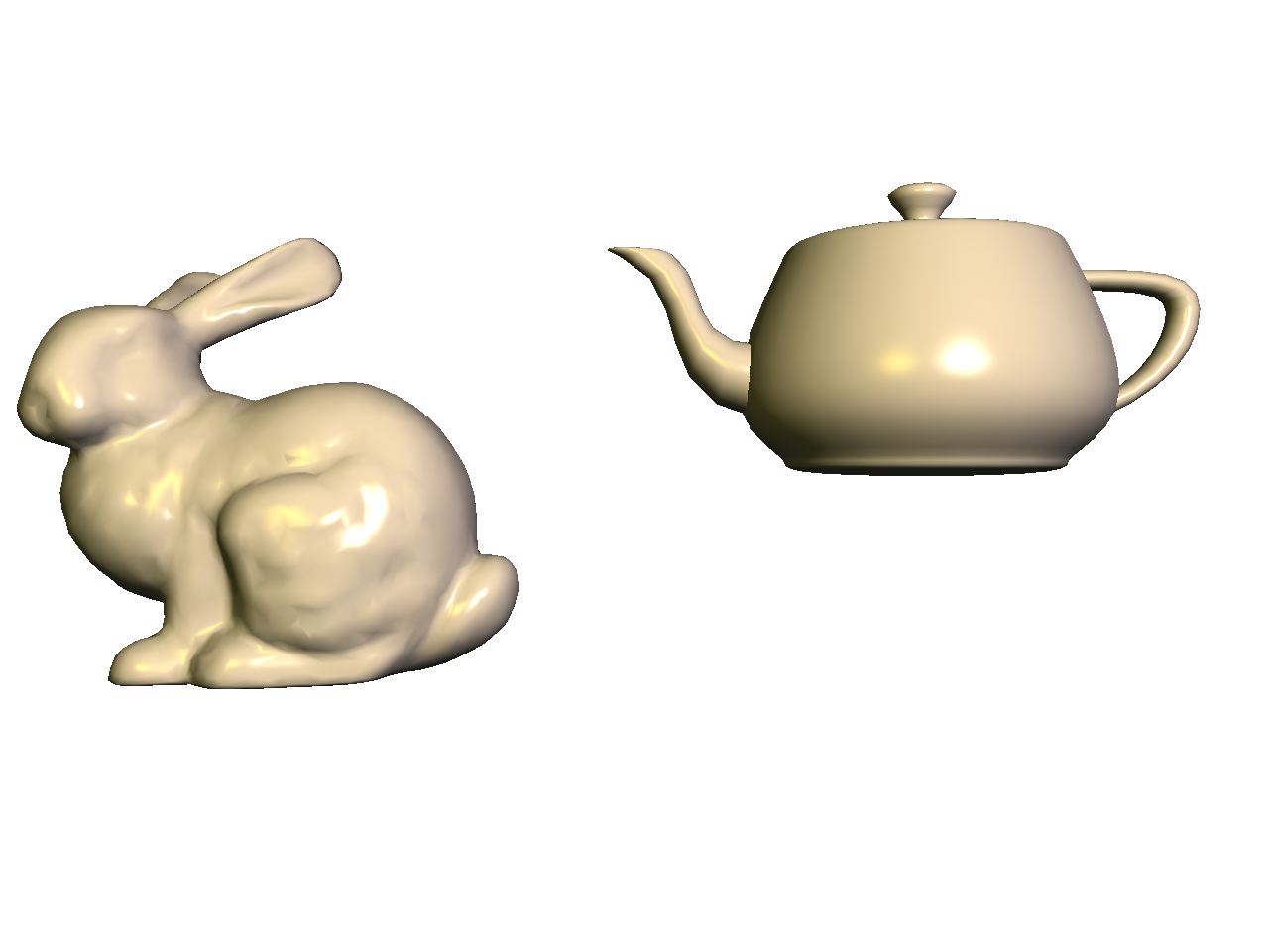
Now shear the teapot, so that it looks like it is about to pour some tea onto the bunny. You can do this with the following code:
glm::mat4 S(1.0f);
S[0][1] = 0.5f;
MV->multMatrix(S);
Remember to use the inverse transpose of the modelview matrix and to normalize the normal in the vertex shader. The interpolated normal should be normalized again in the fragment shader.
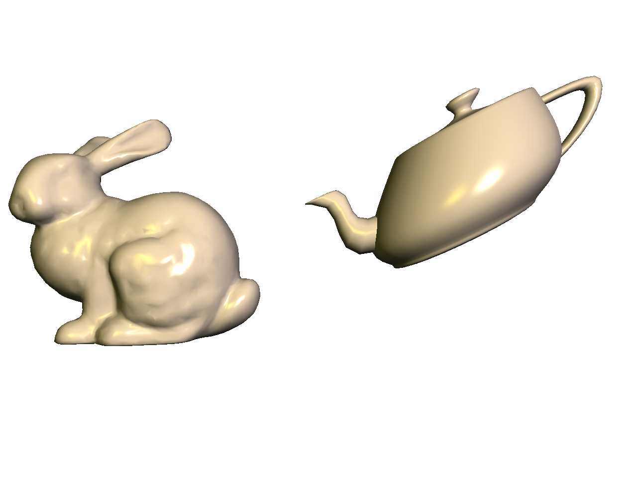
Finally, make the bunny rotate and teapot shear with time, using the time variable t, which is defined in the skeleton code. Pressing the spacebar toggles the value of t to be 0 or the time.
- The bunny should be rotated using
MV->rotate(t, 0.0f, 1.0f, 0.0f);. - The teapot should be sheared using
S[0][1] = 0.5f*cos(t);.
This should make the teapot’s spout dodge the bunny’s ears.
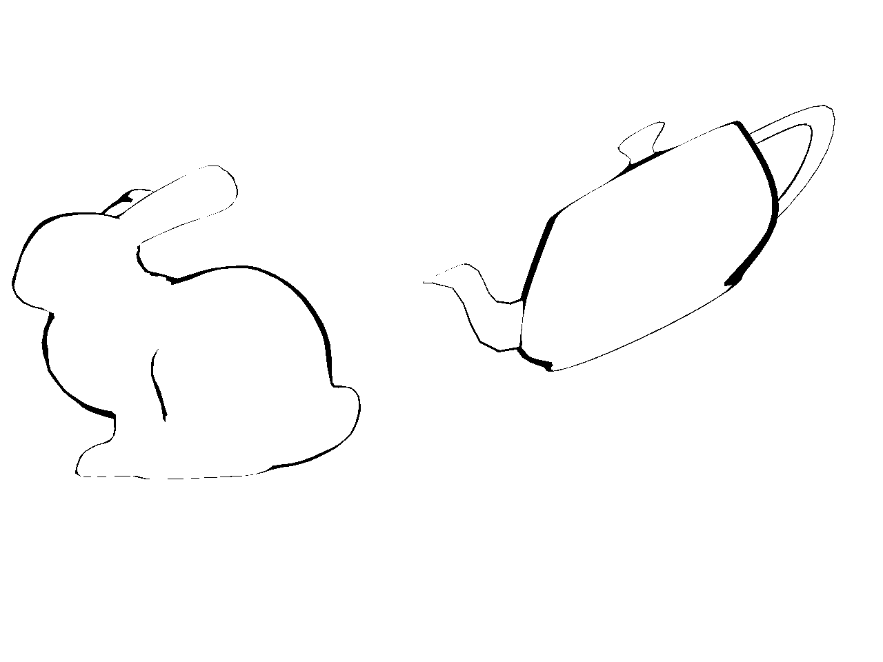
Task 5: Silhouette Shader
Create a silhouette shader. Set up the code so that pressing the s/S keys cycles through the three shaders (Normal, Blinn-Phong, and Silhouette). The silhouette shader should color all fragments white, except for those fragments whose normals form a right angle with the eye vector.

Take the dot product of the normal and eye vectors and threshold the result. If the result is “close enough” to zero, then color that fragment black. Remember that both of these vectors need to be in the camera space. Use 0.3 as the threshold. In other words, if the following is true, then set the color to be black. Otherwise, set the color to be white.
‖�^⋅�^‖<0.3,
where �^ is the normal, and �^ is the eye (view) vector.
Task 6: Cel Shader
Finally, add a cel shader. Set up the code so that pressing the s/S keys cycles through the four shaders (Normal, Blinn-Phong, Silhouette, Cel).
The silhouette should be black, like in the previous task. For non-silhouette areas, quantize the colors into � levels. Quantization should be applied to each of the RGB channels separately. There are many ways to do this, but here is one version that quantizes the red channel into 5 levels:
if(R < 0.25) {
    R = 0.0;
} else if(R < 0.5) {
    R = 0.25;
} else if(R < 0.75) {
    R = 0.5;
} else if(R < 1.0) {
    R = 0.75;
} else {
    R = 1.0;
}
If green and blue are quantized in the same way, this is the result:
Your code should work with all three materials from Task 2.
Since cel shading is often used for artistic purposes, you do not need to get these exact results. The requirements are:
- The three materials must be clearly distinguishable when pressing
m/M. You can even try messing up the colors a bit, for example by inverting the colors. - The light location must be clearly identifiable when rotating the scene.
Interaction summary
m/M: cycle through materialsl/L: cycle through lightsx/X: move selected light in xy/Y: move selected light in ys/S: cycle through shaders
Debugging OpenGL & GLSL
- Set the Program class to be verbose by calling the
setVerbose()function. If there is a GLSL compilation error, then you will see the error in the console. For example, if the varying variables of the vertex shader and the fragment shaders do not match up, it will tell you so. Make sure to set verbose to be false after debugging. - Use
GLSL::checkError(GET_FILE_LINE);to find which OpenGL call caused an error. This function will assert if there were any OpenGL errors before getting to this line. You can use this to winnow down which OpenGL function is causing an error. For example, if you put this line at the top, the middle, and the bottom of your function, and if the assertion happens in the middle, you know that the error must be happening in the top half of your function. Once find exactly which OpenGL call is causing the error, you can Google the OpenGL function to figure out what caused the error. For example, maybe one of the arguments should not have been zero or null.
Point breakdown
Your code only needs to show the highest task completed. In other words, if you complete Task N, points for Tasks 1 through N will be given.
- 10 points for Task 1: transforming the bunny to center it.
- 20 points for Task 2: applying three different materials.
- 20 points for Task 3: using multiple lights.
- 20 points for Task 4: rotating the bunny and adding a shearing teapot.
- 10 points for Task 5: adding a silhouette shader.
- 10 points for Task 6: adding a cel shader.
- 10 points for coding style and general execution. E.g.:
- Hard-coded values must be set in
init(), notrender(). - Inverse transpose must be computed on the CPU, not on the GPU.
- Keyboard interactions must work as specified.
- Hard-coded values must be set in
Total: 100 points
What to hand in
Failing to follow these points may decrease your “general execution” score. On Linux/Mac, make sure that your code compiles and runs by typing:
> mkdir build
> cd build
> cmake ..
> make
> ./A3 ../resources
If you’re on Windows, make sure that you can build your code using the same procedure as in Lab 0.
- Make sure the arguments are exactly as specified.
- Include a README file (ascii only) that includes:
- Your name, UID, and email
- The highest task you’ve completed
- Citations for any downloaded code
- Plus anything else of note
- Remove unnecessary debug printouts.
- Remove unnecessary debug code that has been commented out.
- Hand in
src/,resources/,CMakeLists.txt, and your readme file. The resources folder should contain the obj files and the glsl files. - Do not hand in:
- The build directory
- The executable
- Old save files
(*.~) - Object files
(*.o) - Visual Studio files
(.vs) - Git folder
(.git)
- Create a single zip file of all the required files.
- The filename of this zip file should be
UIN.zip(e.g.,12345678.zip). - The zip file should extract a single top-level folder named
UIN/(e.g.12345678/). - This top-level folder should contain your README,
src/,CMakeLists.txt, etc. - Use the standard
.zipformat (not.gz,.7z,.rar, etc.).
- The filename of this zip file should be
CSCE441 Assignment 4 – Free-Look World
Goals
To become proficient with the use of 3D transforms and projections in OpenGL and to continue working with Blinn-Phong shading. Specifically, you will:
- Create a 3D world you can walk through, with multiple transformed objects.
- Implement freelook for camera motion.
- Create a HUD (heads up display).
- Show a top-down view of the world showing the camera and the frustum.
- Use a textured material with Blinn-Phong lighting.
Associated Labs
- Lab 0 (required): Setting Up Your Development Environment
- Lab 8 (L08’s Task 1 is recommended for A4’s Task 6): Texture mapping
- Lab 9 (L09’s Task 1 is recommended for A4’s Task 6): Texture mapping and lighting
Task 1: Setting up the World
There is no base code provided for this assignment. Please start with your previous lab/assignment code. Please come see the instructor or the TA if you need help completing your previous assignment.
Write some code so that you can add multiple objects to the world. Each object should have some member variables so that you can easily translate/rotate/scale/shear the object in the world. (Remember that to transform the normals properly, you’ll need to send the inverse transpose matrix as a parameter to the shader if you include shear or non-uniform scales.) For this initial stage, since we’re using the default camera from previous assignments/labs, the objects that you add to the world may have to be scaled small so that they’re visible from the camera. Once you implement freelook later in this assignment, you may need to re-transform these objects to distribute them in the world the way you want.
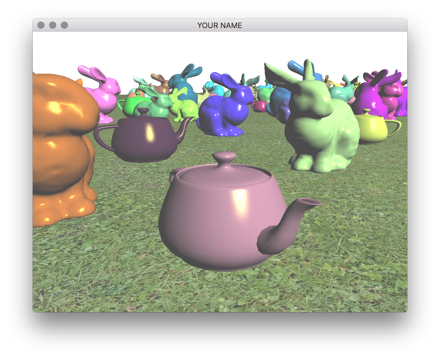
You should include at least two types of shapes. For example, here I’m using the bunny and the teapot shapes. You can use any model, but please try to keep the file sizes reasonable. If you download a model, please put a citation in your readme. Note that some OBJ files may not come with normals or texture coordinates.
You should add at least 100 things in the scene and a ground plane. These objects should be distributed (roughly) equally on the ground plane. (E.g., do not put them in a straight line.) It is important to load each OBJ file just once, even if you are going to draw that shape multiple times. One good way to do this is to create a new class that has a pointer/reference to a Shape instance. Each object must be translated so that the bottom of the object touches the ground. To do this, you will need the most negative Y coordinate of the mesh.
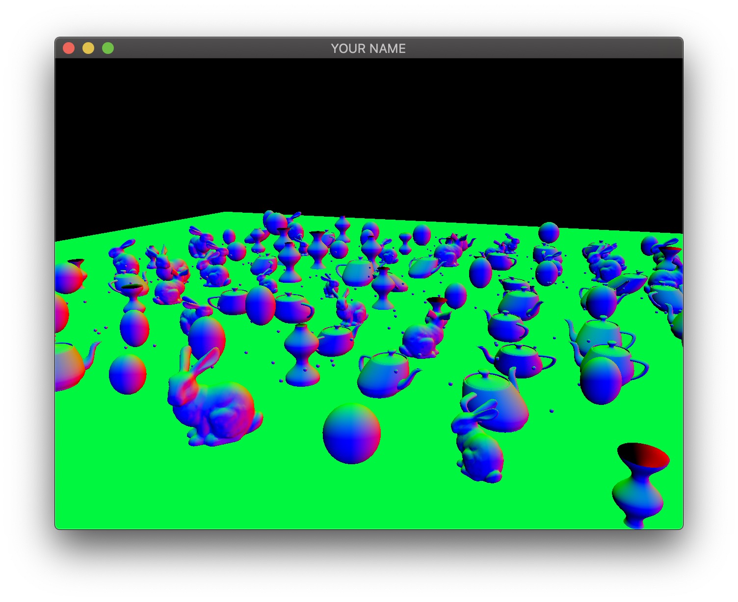
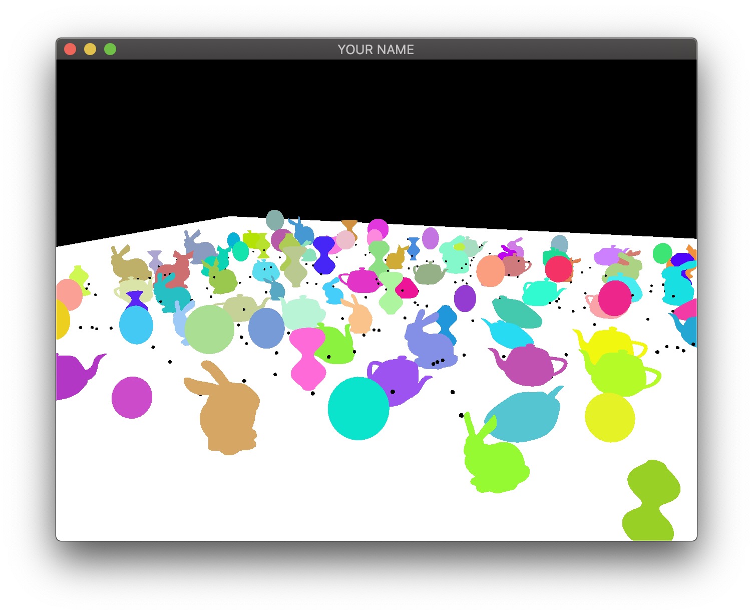
Use your Blinn-Phong shader from your previous assignment to shade the models. The objects should be assigned random colors. Unlike the last assignment, the light position should be fixed in the world. This means that the light position is no longer a constant in camera space. You need to choose a world space position for the light and then multiply this position by the view matrix (modelview matrix before adding any modeling transforms) to transform the light position into camera space. The camera-space light position should then be sent to the fragment shader as a uniform variable.
Finally, draw a sphere (the sun) where the light is. The lighting on the objects in the scene should match this location of the light source. In the image below, note how the left side of the green bunny is correctly lit by the light in the upper left corner of the image.
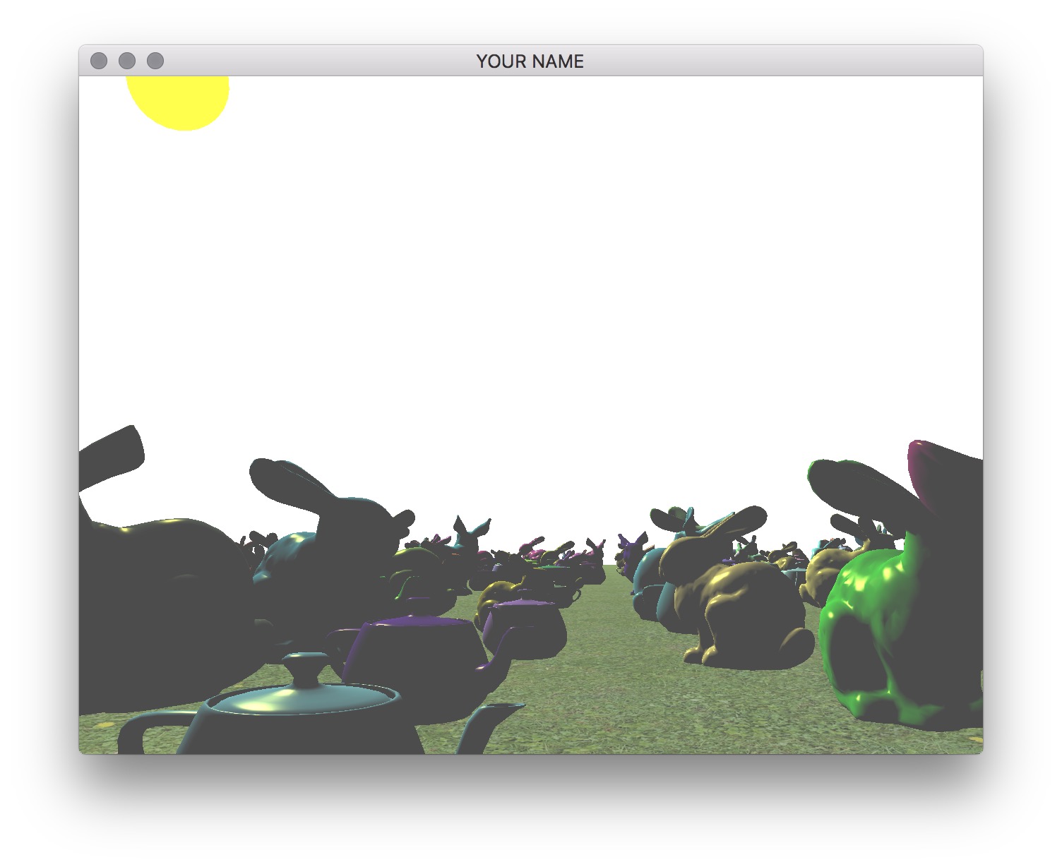
The shader for drawing the light can be the same Blinn-Phong shader as for the other models. You can set the ambient color to be the color of the sun, and diffuse and specular colors to be zero.
Task 2: Freelook Camera
Now replace the Camera class with your own class that implements freelook. You can reuse the applyProjectionMatrix() method, but you’ll need to modify the applyViewMatrix() method. To implement freelook, the new camera class needs to keep track of its position, yaw, and pitch. From these three quantities, you need to come up with the correct arguments for the glm::lookAt() function.
The general setup of your code should be as follows:
- When a key is pressed or the mouse is moved, the camera’s translation, yaw, and pitch should be updated. For event handling, use your previous labs and assignments, as well as the GLFW Input guide.
- In the
render()method inmain.cpp, the first matrix in the modelview matrix stack should be filled by theapplyViewMatrix()method of your new freelook camera class. In theapplyViewMatrix()method, you should use theglm::lookAt()method to create this view matrix.
The eye, target, and up arguments of the lookAt() function are:
eye: camera positiontarget: camera position + “forward” directionup: the Y vector, (0,1,0), (assuming Y-up)
Position
I suggest fixing yaw and pitch first so that you can get basic translation correct with no rotation. The initial position of the camera should incorporate the height of the camera off of the ground.
Add keyboard hooks for WASD for translation:
w: move forwarda: move lefts: move backwardd: move right
Pressing these keys should update the translation of the camera.
For now, the “forward” direction can be set to the negative Z direction, which is the default camera direction in OpenGL. When the w key is pressed, the camera should move along this “forward” direction. In the applyViewMatrix() method of your camera class, feed this new translation value into the lookAt() function.
Yaw
Now add yaw to your freelook camera, which allows you to look right and left. The X-motion of the mouse should be tied to the yaw angle of the camera. Look at the previous camera class from the labs to see how mouse inputs are handled.
The “forward” direction should be computed based on the yaw angle. If the ground is on the �=0 plane, then the forward direction is
�→=(sin(�)0cos(�)),
where � is the yaw angle. The w key should now move the camera along this new “forward” direction, rather than the negative Z direction. The “left” direction (or the “right” direction) can be computed using the cross product: “right” = “forward” cross “up”. If this is working properly, pressing the w key should move the camera forward, and pressing the d key should move the camera to the right, no matter which way it is facing with respect to the world.
Pitch
Finally, add the pitch angle, which allows you to look up and down. The Y-motion of the mouse should be tied to the pitch angle of the camera. Unlike the yaw angle, the pitch angle should be capped at some reasonable limits (e.g., -60 to +60 degrees). The pitch angle should change the “target” argument of the lookAt() method, since it changes the “forward” direction that the camera is looking at. In other words, when computing the “target” argument, the “forward” vector should have a Y component that depends on the pitch angle. However, the pitch angle should not change the direction of motion. Even if the camera is looking up or down, pressing w should not change the height of the camera. (The camera should not lift off of or go into the ground.)
Zoom
Add zooming functionality to the camera using the z/Z keys (zoom in and zoom out). Pressing these keys should change the field of view in Y (FOVY) of the camera. The field of view should be capped between 4 degrees and 114 degrees. These correspond to roughly 600 mm and 14 mm lenses for full-frame cameras.
Depending on which skeleton code you start from, the z key may already be mapped to enable wireframe display mode. If so, delete or comment out the code to change the glPolygonMode(...) in the render function.
Task 3: Transform Objects with Time
Transform the objects over time using the glfwGetTime() function. (See the image below.)
- Apply a scale using sine/cosine so that the objects grow and shrink over time.
- Translate the objects appropriately so that the object is just touching the ground plane at all times.
Task 4: Heads Up Display
Add a head-up display (HUD) that shows objects (e.g., bunnies) on the two upper corners of the screen.
- These objects should rotate in place.
- These objects should stay in the upper corners when the window size is changed.
- Use the Blinn-Phong shader for the HUD objects, with the light defined in camera space.
Task 5: Top-Down View
Now we’re going to add a “top-down” orthographic view. As the camera moves around the world, this top-down view should show where the camera is and which direction it is pointing.
Add Another Viewport
First, add a second viewport to the lower left of the screen. This viewport should be activated/deactivated by pressing the t key. Within this viewport, draw the scene objects (models, ground, sun) again but with different projection and view matrices. The pseudocode for the render() function is as follows:
// Main viewport (your current code should be doing something like this already)
glViewport(0, 0, width, height);
P->pushMatrix();
MV->pushMatrix();
APPLY PROJECTION MATRIX FOR MAIN VIEWPORT
APPLY VIEW MATRIX FOR MAIN VIEWPORT
DRAW SCENE
MV->popMatrix();
P->popMatrix();

// Top-down viewport (new code for this task)
if top-down view activated
    double s = 0.5;
    glViewport(0, 0, s*width, s*height);
    glEnable(GL_SCISSOR_TEST);
    glScissor(0, 0, s*width, s*height);
    glClear(GL_COLOR_BUFFER_BIT | GL_DEPTH_BUFFER_BIT);
    glDisable(GL_SCISSOR_TEST);
    P->pushMatrix();
    MV->pushMatrix();
    APPLY PROJECTION MATRIX FOR TOP-DOWN VIEWPORT
    APPLY VIEW MATRIX FOR TOP-DOWN VIEWPORT
    DRAW SCENE
    MV->popMatrix();
    P->popMatrix();
end
Some notes about this pseudocode:
- The width and height variables can be obtained with
glfwGetFramebufferSize(window, &width, &height);. - OpenGL’s “scissor” test is used to clear just a portion of the screen corresponding to the 2nd viewport.
- The lines “apply projection matrix” and “apply view matrix” for the main viewport correspond to the methods in your camera class from the previous tasks.
- The projection matrix for the top-down viewport should be constructed with a call to
P->multMatrix(glm::ortho(...))(see the documentation on the ortho function here). - The view matrix for the top-down viewport should be constructed manually with
MV->translate(...)andMV->rotate(...). By default, the camera is at the origin, looking down the negative Z-axis. For this viewport, you need the camera’s origin to be above the X-Z plane, looking down the negative Y-axis. - Do not draw the HUD for the top-down viewport.
Draw the Frustum
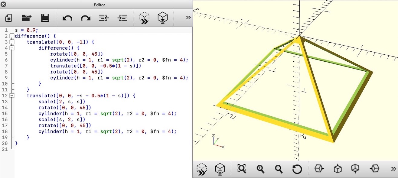
Next, draw the view frustum in the top-down view. To create the mesh for the frustum, we’ll be using OpenSCAD. Download, install, and start the application, and then copy the following code into the editor.
s = 0.9;
difference() {
    translate([0, 0, -1]) {
        difference() {
            rotate([0, 0, 45])
            cylinder(h = 1, r1 = sqrt(2), r2 = 0, $fn = 4);
            translate([0, 0, -0.5*(1 - s)])
            rotate([0, 0, 45])
            cylinder(h = 1, r1 = sqrt(2), r2 = 0, $fn = 4);
        }
    }
    translate([0, 0, -s - 0.5*(1 - s)]) {
        scale([2, s, s])
        rotate([0, 0, 45])
        cylinder(h = 1, r1 = sqrt(2), r2 = 0, $fn = 4);
        scale([s, 2, s])
        rotate([0, 0, 45])
        cylinder(h = 1, r1 = sqrt(2), r2 = 0, $fn = 4);
    }
}
Then follow these steps in OpenSCAD:
- ‘View’ –> ‘View All’ (optional, to see the object better)
- ‘Design’ –> ‘Render’
- ‘File’ –> ‘Export’ –> ‘Export as STL…’
Open the STL file in MeshLab. Uncheck the option to ‘Unify Duplicated Vertices in STL files’ because we want to retain the hard corners. Then:
- ‘File’ –> ‘Export Mesh As…’
- Choose ’Alias Wavefront Object (*.obj)’
The left image below shows the exported mesh.
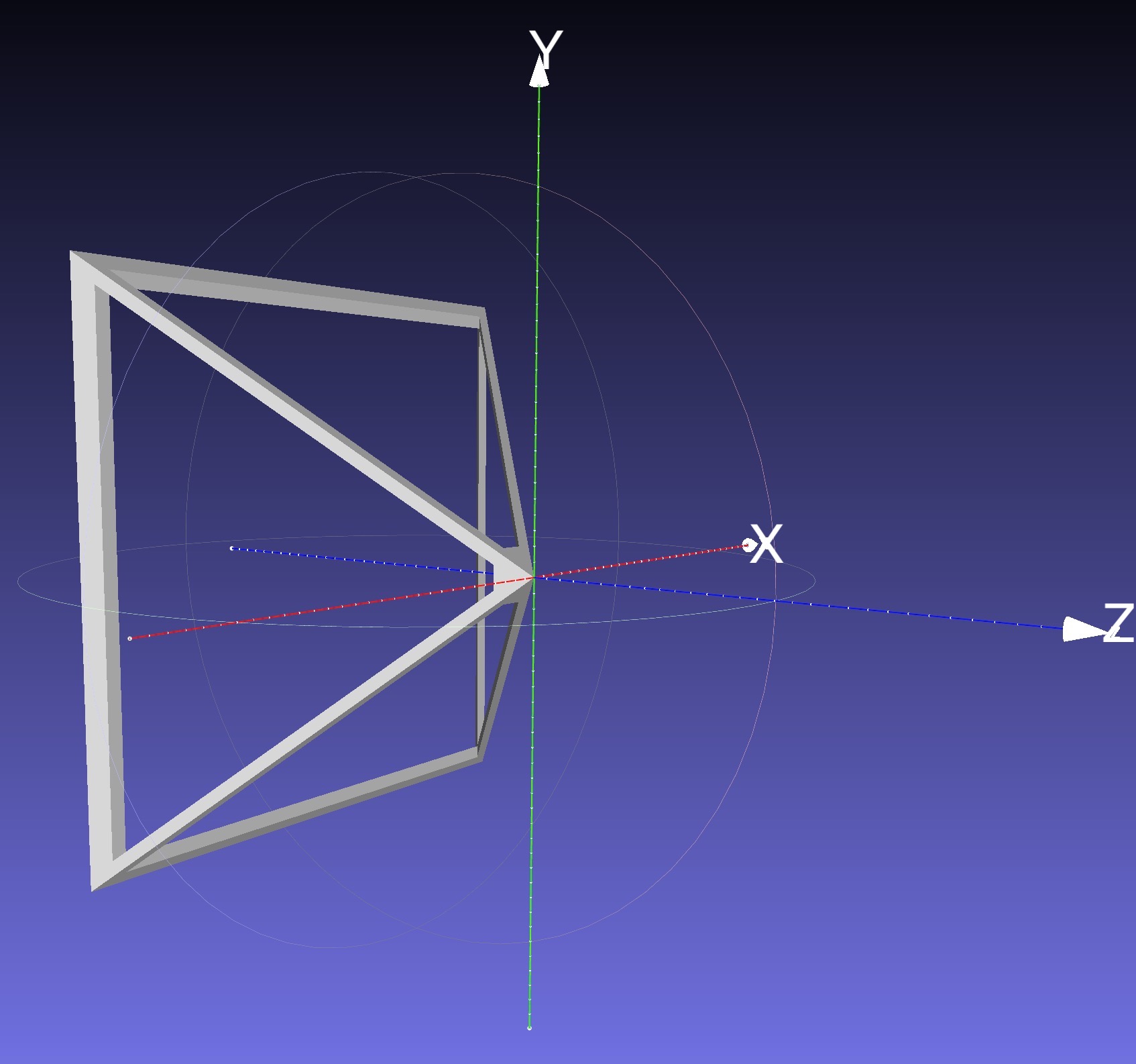
First, draw this mesh in the top-down viewport without applying any model transform to it. It should appear at the world origin, looking down the negative Z axis. Now, to account for the translation and the rotation of the camera, use the inverse of the view matrix (i.e., the camera matrix) as the model matrix when drawing the camera. This camera matrix should be multiplied onto the matrix stack before drawing the frustum. The following pseudocode should be added to the DRAW SCENE line of the top-down viewport portion of the first pseudocode of this task:
pushMatrix()
Camera matrix = inverse of the view matrix
multMatrix(Camera matrix)
Send the top matrix to the GPU
Draw the frustum
popMatrix()
The inverse of the view matrix can be obtained by inverting the output matrix of the glm::lookAt(...) function.
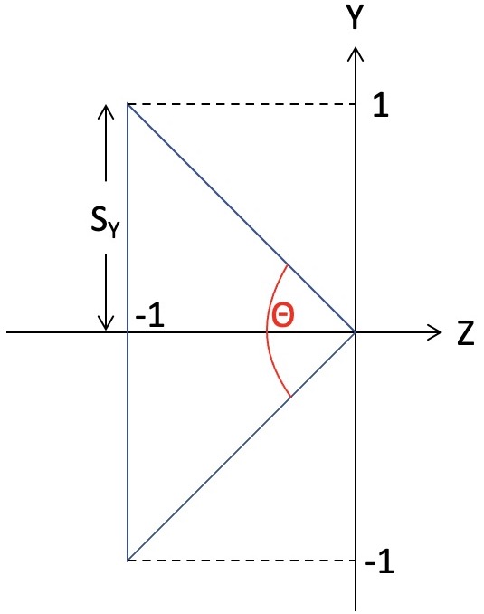
As shown in the right image above, the frustum’s extent is −1 to +1 in Y (as well as X) and 0 to −1 in Z, which means that the shape of this frustum is correct only when the field of view is �=90 degrees. To fix this, the following scales should be applied in X and Y:
��=�tan(�2),��=tan(�2),
where �=width/height is the aspect ratio of the frame buffer. The angle, �, is the field of view of the main camera, which depends on the current zoom level. The scale values �� and �� should be applied to the modelview matrix stack before drawing the frustum.
Optionally, to make visible the parts of the frustum below the ground, disable the depth test while drawing the frustum:
glDisable(GL_DEPTH_TEST);
Transform and draw the frustum
glEnable(GL_DEPTH_TEST);
Task 6: Texture
Add a texture to the ground. You can use the vertex buffer approach from Lab 8 or use square.obj from Lab 9. You can also download a mesh (and add a citation in your readme), but note that some OBJ files may not come with normals or texture coordinates.
Point breakdown
- 20 points for Task 1
- 10 points for populating the world with multiple objects (≥2 types, ≥100 total objects) and the ground. Objects must be properly grounded.
- 5 points for Blinn-Phong with world light position. Objects must have random colors.
- 5 points for drawing the sun.
- 30 points for Task 2
- 5 points for freelook translation.
- 10 points for freelook yaw.
- 10 points for freelook pitch. The camera must not go into or fly off of the ground.
- 5 points for freelook zoom.
- 10 points for Task 3: transforming objects with time. Objects must remain properly grounded.
- 10 points for Task 4: HUD.
- 20 points for Task 5
- 10 points for top-down viewport.
- 10 points for camera frustum.
- 5 points for Task 6: texturing the ground.
- 5 points for coding style and general execution (e.g., loading each OBJ only once, etc.).
Total: 100 points
What to hand in
Failing to follow these points may decrease your “general execution” score. On Linux/Mac, make sure that your code compiles and runs by typing:
> mkdir build
> cd build
> cmake ..
> make
> ./A4 ../resources
If you’re on Windows, make sure that you can build your code using the same procedure as in Lab 0.
For this assignment, there should be only one argument. You can hard code all your input files (e.g., obj files) in the resources directory.
- Make sure the arguments are exactly as specified.
- Include an ASCII README file that includes:
- Your name, UID, and email
- The highest task you’ve completed
- Citations for any downloaded code
- Plus anything else of note
- Make sure you don’t get any compiler warnings.
- Remove unnecessary debug printouts.
- Remove unnecessary debug code that has been commented out.
- Hand in
src/,resources/,CMakeLists.txt, and your readme file. The resources folder should contain the obj files and the glsl files. - Do not hand in:
- The build directory
- The executable
- Old save files
(*.~) - Object files
(*.o) - Visual Studio files
(.vs) - Git folder
(.git)
- Create a single zip file of all the required files.
- The filename of this zip file should be
UIN.zip(e.g.,12345678.zip). - The zip file should extract a single top-level folder named
UIN/(e.g.12345678/). - This top-level folder should contain your README,
src/,CMakeLists.txt, etc. - Use the standard
.zipformat (not.gz,.7z,.rar, etc.).
- The filename of this zip file should be
CSCE441 Assignment 5 – Dynamic Geometry & Deferred Rendering
Goal
- Attenuated lights
- Various types of dynamic 3D transforms (rotation, shears, transformation order, etc.)
- A static surface of revolution on the CPU
- A dynamic surface of revolution on the GPU
- Deferred rendering
- (Bonus) Tiled deferred rendering
NOTE: For maximum compatibility with student computers/drivers, we are only going to use OpenGL 2.1.
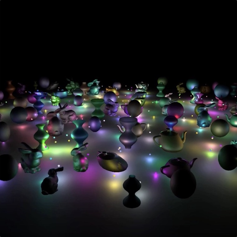
(The graininess is due to the video compression – better quality video here.)
Associated Labs
- Lab 0 (required): Setting Up Your Development Environment
- Lab 10 (recommended for Task 4): Sphere with Squash and Stretch
- Lab 11 (recommended for Task 5): Surface of Revolution
- Lab 12 (recommended for Task 6): Multiple Render Targets
Task 1: Multiple Attenuated Lights
There is no base code provided for this assignment. Please start with your previous lab/assignment code. Please come see the instructor or the TA if you need help completing your previous assignment.
- Start with your A3 or A4 code.
- If starting from A4, strip away the code for HUD, texture, and the top-down view.
- If starting from A3, replace the lighting model to be like in A4 – the light source should be defined in world coordinates rather than in camera coordinates.
- Add at least 100 objects in the scene.
- Each object should have a random diffuse color.
- Each object should have a random scale.
- Replace the ambient color with the object’s “emissive” color, which will be used for rendering the lights. For these 100+ objects, the emissive color should be zero.
- You can hard code the specular color to (1,1,1) with exponent 10.
- Distribute these objects to an area of about 10×10 units on the XZ plane, centered about the origin of the world. (E.g., do not put them in a single line.)
- Add at least 10 lights, each with a color.
- Change the background color to black with
glClearColor(0.0f, 0.0f, 0.0f, 1.0f);in the init function. - To compute the fragment color in the shader, compute the diffuse and specular RGB color as before in A4 (but with no ambient), and then multiply its three color components by the corresponding color components of the light.
- The lights’ uniform parameters should be passed as an array of
glm::vec3s to the fragment shader. You can use the following syntax:glUniform3fv(uniformID, count, value_ptr(array[0]));, whereuniformIDis the ID pointing to the uniform variable in the shader (e.g.,prog->getUniform("foo"))),countis the array length, andarrayis the array ofglm::vec3s. In the shader, the array should be declared asuniform vec3 foo[10], assuming thatcount=10. - The vertical position of each light (i.e., its y coordinate) should be around half the height of the objects. (See images above.)
- Change the background color to black with
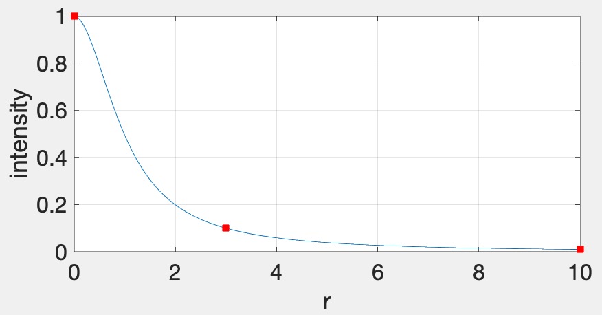
- Now add attenuation to the lights. We’re going to use the standard quadratic attenuation model in OpenGL:�=1�0+�1�+�2�2,where � is the distance between the fragment and the light, and �0, �1, �2 are the constant, linear, and quadratic attenuation factors. For this part of the assignment, we want the light to fall off to 10% of its strength at �=3 and to 1% at �=10, which gives us �0=1.0, �1=0.0429, and �2=0.9857. The color at the fragment should be scaled by this attenuation value.
vec3 fragColor = ke; // emissive color of the object (see below) for(...) { // for each light float diffuse = ...; float specular = ...; vec3 color = lightColor * (kd * diffuse + ks * specular); float attenuation = 1.0 / (A0 + ...); fragColor += color * attenuation; } - Each light should be displayed as a sphere, using the same fragment shader as everything else. We’ll use the “emmissive” color, ��, for this, which is the color that the light is emitting. This value should be set to the light color when rendering the sphere for the light and (0,0,0) for everything else. Putting everything together, the fragment color for all objects and lights should be computed as follows:�→�+∑��→�⊙�→�max(0,�^⋅�^�)+�→�max(0,(�^⋅ℎ^�)�)�0+�1��+�2��2,where � is the ith light. The ⊙ notation indicates that the multiplication should be done component-wise, for R, G, and B. This equation allows us to use a single shader to render everything in the scene – the lights will be colored using ��, and other objects will be colored with attenuated Blinn-Phong. To summarize:
- When rendering the lights, set �→� to be the color of the light and set �→� and �→� to be zero.
- When rendering the other objects, set �→� to be zero and set �→� and �→� to be the objects’ material parameters.
Task 2: Rotating Bunnies
Rather than changing the scale of the bunny over time as in A4, rotate it around its vertical axis. As in A4, the overall scale of the bunny should still be randomized, and the bunny should touch the floor but not intersect it.
In this image (and the following), I am using only one light to better illustrate the motion.
Task 3: Shearing Teapots
Rather than changing the scale of the teapot over time as in A4, shear it so that it sways from side to side. The teapot should look like it is glued to the floor. As in A4, the overall scale of the teapot should still be randomized.
Task 4: Bouncing Spheres
Add some bouncing spheres, following the steps outlined in Lab 10. The sphere should have a randomized radius, and it should touch the floor but not intersect it. When the sphere is moving up or down, its scale in X and Z should be made smaller to achieve “squash and stretch.” The geometry of the sphere should be created and stored in memory just once in the init() function. To display multiple spheres in the scene, use different transformation matrices passed in as uniform variables.
Task 5: Surface of Revolution
Add some surfaces of revolution, following the steps outlined in Lab 11. First, implement a static surface on the CPU and then move the computation over to the GPU to allow a dynamic surface. Like the sphere, the vertex attributes of the surface of revolution should be created just once in the init() function. To display multiple surfaces of revolution in the scene, use different transformation matrices passed in as uniform variables. Just like the other objects in the scene, the surface-of-revolution objects should just touch the ground.
Task 6: Deferred Rendering
We are now going to implement deferred rendering. Since this step requires render to texture and multiple render targets, it may help to complete Lab 12 first. Deferred rendering will require substantial overhauling of your code base, so you should make sure to apply source control so that you can easily get back to your old code if needed.
In deferred rendering, we use two passes. In the first pass, we render to multiple render targets to create textures that hold all the information needed to compute the color of each fragment. In the second pass, we render a view-aligned quad with the textures from the first pass, and then do the actual lighting computation in the fragment shader.
First Rendering Pass
The four images below show the four textures we need to generate in the first pass. The size of these textures should be the same as the onscreen framebuffer size, which can be obtained with glfwGetFramebufferSize(...). (The default size is 640 x 480; later, support for resizing the window will be added.)
- The first image is the camera-space position of all of the fragments. In this visualization, the position (�,�,�) is coded with (�,�,�). Since RGB needs to be between 0 and 1, the visualization shows a black area in the lower left, corresponding to the region where the camera-space positions are all negative. Also, since the camera-space Z coordinate of all of these fragments are negative, there is no blue component in the color output of any of the fragments.
- The second image is the camera-space normal of all of the fragments. As before, the normal’s (�,�,�) is coded with (�,�,�). Fragments whose normals are pointing to the right in camera-space are colored red, those whose normals are pointing up are colored green, and those whose normals are pointing toward the camera are colored blue.
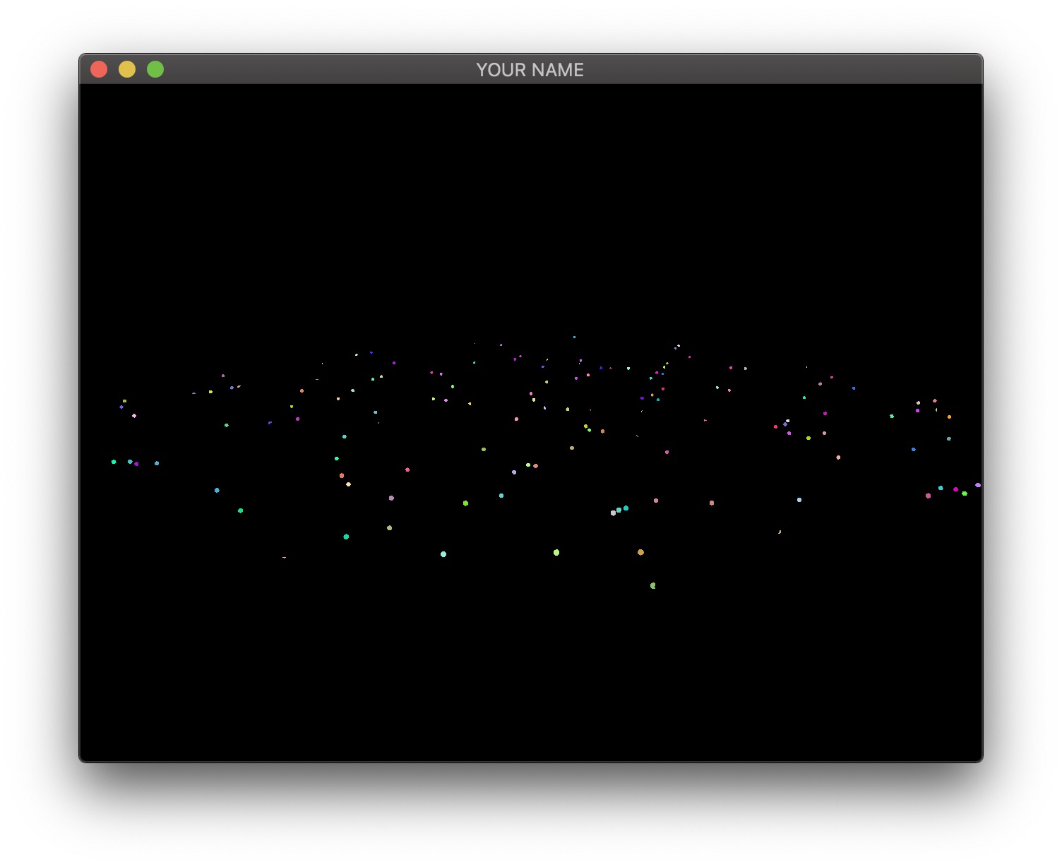
- The third image is the emissive color of all the fragments. In this image, I have 200 randomly colored lights, but in your code, you may only have a small number of lights.
- The fourth image is the diffuse color of all the fragments.
These four textures must be generated as the output of the first pass. To do so, first, change the texture format in your C++ code to use 16 bit floats: GL_RGB16F instead of GL_RGBA8, and GL_RGB instead of GL_RGBA.
// L12
glGenTextures(1, &texture);
glBindTexture(GL_TEXTURE_2D, texture);
glTexImage2D(GL_TEXTURE_2D, 0, GL_RGBA8, width, height, 0, GL_RGBA, GL_FLOAT, NULL);
...
// A5: replace the last line above with this:
glTexImage2D(GL_TEXTURE_2D, 0, GL_RGB16F, width, height, 0, GL_RGB, GL_FLOAT, NULL);
In this assignment, there are four textures, so the line above must be used four times. The fragment shader of the first pass can now write floating point values to the four textures:
#version 120

varying vec3 vPos; // in camera space
varying vec3 vNor; // in camera space

uniform vec3 ke;
uniform vec3 kd;

void main()
{
    gl_FragData[0].xyz = vPos;
    gl_FragData[1].xyz = vNor;
    gl_FragData[2].xyz = ke;
    gl_FragData[3].xyz = kd;
}
The vertex shaders for the first pass depends on what is being drawn. Bunny, teapot, and sphere should be drawn with a simple vertex shader that transforms the position and normal into camera space (vPos and vNor in the fragment shader above). Surface of revolution will require another vertex shader.
Second Rendering Pass
In the second pass, we draw a view-aligned quad that completely fills the screen. In this stage of the assignment, we can simply draw a unit square somewhere close enough to the camera so that it ends up covering the whole screen. The vertex shader for the second pass is very simple:
#version 120

uniform mat4 P;
uniform mat4 MV;

attribute vec4 aPos;

void main()
{
    gl_Position = P * (MV * aPos);
}
This vertex shader simply transforms the vertex position from model space to clip space. The fragment shader will use the textures created in the first pass to compute the final fragment colors that end up on the screen. Rather than using the texture coordinates of the quad, we can compute them in the fragment shader using the keyword gl_FragCoord, which stores the window relative coordinate values for the fragment. Dividing this by the window size gives the correct texture coordinates, which is (0,0) at the lower left corner and (1,1) at the upper right corner. Using these texture coordinates, read from the four textures and then calculate the color of the fragment. Additionally, you need to pass in the light information to this fragment shader as uniform variables (e.g., light positions and colors).
#version 120

uniform sampler2D posTexture;
uniform sampler2D norTexture;
uniform sampler2D keTexture;
uniform sampler2D kdTexture;
uniform vec2 windowSize;

... // more uniforms for lighting

void main()
{
    vec2 tex;
    tex.x = gl_FragCoord.x/windowSize.x;
    tex.y = gl_FragCoord.y/windowSize.y;

    // Fetch shading data
    vec3 pos = texture2D(posTexture, tex).rgb;
    vec3 nor = texture2D(norTexture, tex).rgb;
    vec3 ke = texture2D(keTexture, tex).rgb;
    vec3 kd = texture2D(kdTexture, tex).rgb;

    // Calculate lighting here
    ...
    gl_FragColor = ...
}
For debugging, consider these substeps.
- In the fragment shader for the second pass, simply color the quad red (
gl_FragColor.rgb = vec3(1.0, 0.0, 0.0);). This should give you a fully red screen. - Color the fragment using the computed texture coordinates (
gl_FragColor.rg = tex;). The screen should look red/green. - Color the fragment using each texture (e.g.,
gl_FragColor.rgb = pos;). You should see the 4 images at the beginning of this task.
Please set up the code so that the grader can easily produce the 4 images at the top of this section. To get full points, the final output, as well as these 4 images must be correct. Please put in your README file how to produce these images (e.g., “Uncomment line XX in some shader file.”).
HINT: Debugging OpenGL & GLSL
- Set the Program class to be verbose by calling the
setVerbose()function. If there is a GLSL compilation error, then you will see the error in the console. For example, if the varying variables of the vertex shader and the fragment shaders do not match up, it will tell you so. Pay attention to the line number (e.g., line 28 in the error log below). Make sure to set verbose to be false after debugging.Shader InfoLog: ERROR: 0:28: ... ... - Use
GLSL::checkError(GET_FILE_LINE);to find which OpenGL call caused an error. This function will assert if there were any OpenGL errors before getting to this line. You can use this to winnow down which OpenGL function is causing an error. For example, if you put this line at the top, the middle, and the bottom of your function (shown below), and if the assertion happens in the middle, you know that the error must be happening in the top half of your function. You can then keep interspersing thecheckErrorline into more places into the code. Once you find exactly which OpenGL call is causing the error, you can Google the OpenGL function to figure out what caused the error. For example, maybe one of the arguments should not have been zero or null.void render() { GLSL::checkError(GET_FILE_LINE); Some OpenGL lines GLSL::checkError(GET_FILE_LINE); More OpenGL lines GLSL::checkError(GET_FILE_LINE); } - The GLSL compiler will silently optimize away any variables that are not used in the shader. If you try to access these variables at runtime, the program will crash, since these variables no longer exist in the shader. In this lab, when you move the computation of the normal to the GPU, the
aNorvariable no longer needs to be passed to the GPU, since it is computed in the shader. Therefore, you will have to comment out any reference toaNorfrom your C++ runtime code. Or, you can trick the GLSL compiler from optimizing awayaNorby using it and disgarding it as follows:vec3 nor = aNor.xyz; nor.x = ...; nor.y = ...; nor.z = ...;
Bonus: Window Resizing
Add support for window resizing for deferred rendering. Use the framebuffer size callback in GLFW. Note that the code will slow down a lot if the window size is increased, since there are many more fragments to be processed.
Bonus: Tiled Deferred Rendering
In this bonus task, we are going to increase the number of lights. First, because we are going to have many more lights, we are going to adjust the attenuation factor for this part of the assignment. Otherwise the scene will be over-exposed (too bright). Now, we want the light to fall off to 10% of its strength at �=0.3 and to 1% at �=1.0, which gives us �0=1.0, �1=0.4286, and �2=98.5714.
First, implement the naive approach, which uses a for-loop to go through all of the lights in the fragment shader. This is the ground truth, but this will become much too slow as the number of lights increases.
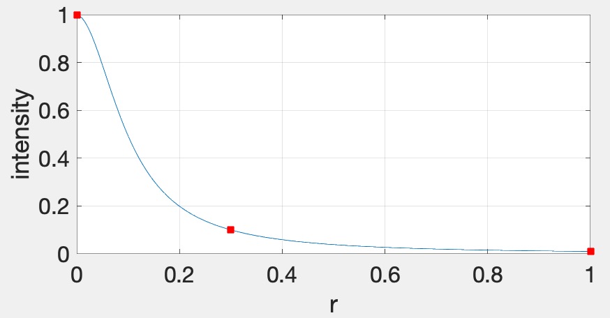
Therefore, we will now use tiled deferred rendering. The basic idea is to render a grid of small quads instead of one big quad that fills the screen. Each small quad will be rendered with only a subset of lights that affect the fragments within that quad. The images below show quads with black borders to visualize the grid. The various shades of red indicate the number of lights each quad is using.
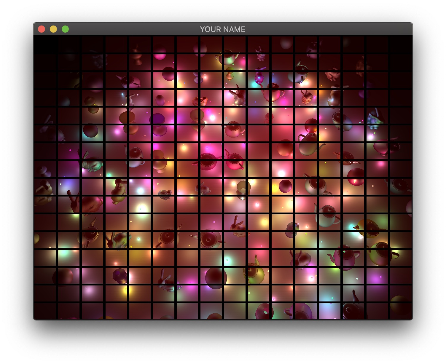
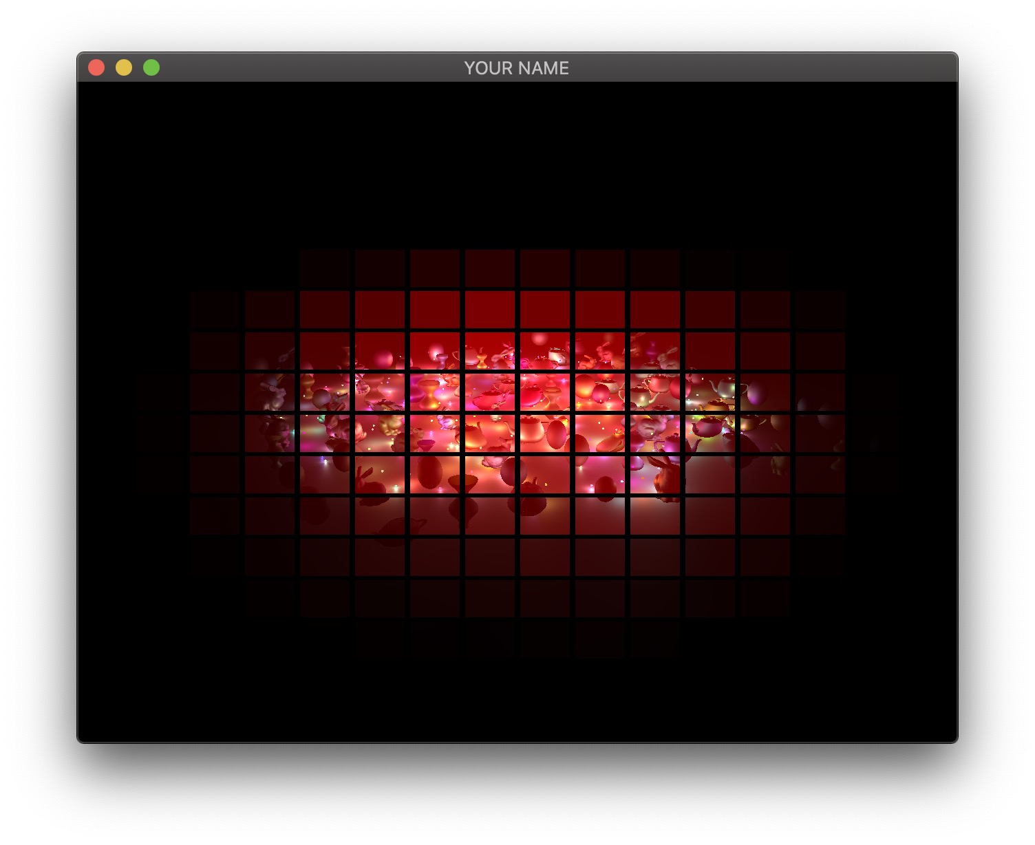
For each quad, we need to know which lights need to be included. To do this, we perform frustum-sphere intersection tests.
- Each 2D quad on the screen is a 3D frustum in world space. The quad must be drawn somewhere between the near and far planes, and the size of the quad depends on exactly where it is drawn. In my implementation, I draw my quads half way between the near and far planes.
- We will assume that each light has a sphere of influence of radius 1, since the intensity of each light falls to 1% of its strength at distance �=1.
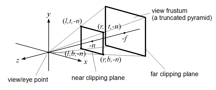
The image above shows a view frustum originating at the camera and sandwiched between the near and far planes. The near and far distances are stored in the Camera class, if you’re using it. (Both � and � are negated because by convention these are defined to be positive distances away from the camera, but the actual near and far planes are along the negative Z axis in camera space.) The corners of the near plane are defined by left, right, bottom, and top (�, �, �, and �). In the previous lab/assignment code, we have been using the field-of-view (fovy) and aspect arguments. To convert this to (�,�,�,�), use the following:
l = -n * tan(fovy/2) * aspect;
r = -l;
b = -n * tan(fovy/2);
t = -b;
Once the overall view frustum for the whole window is derived, divide it into smaller frustums, one for each tile. For each small frustum, perform a frustum-sphere intersection test.

![[Wikimedia]](https://commons.wikimedia.org/wiki/File:John_Tenniel-_Alice%27s_mad_tea_party,_colour.jpg)
The image above shows a schematic of frustum-sphere intersections. For this assignment, each light sphere is of unit radius because of the attenuation factors chosen. For each frustum, check which light spheres intersect it, and then when rendering the quad for this frustum, only include the intersecting lights.
For the intersection tests, use the code by Daniel Holden. (You may need to pass arguments by reference to get good performance.) This piece of code requires you to specify the 6 planes of the frustum. I suggest using camera space to specify both the frustum and the spheres. To specify a frustum plane, you need to specify a point and a direction. For example, the near plane of the frustum can be defined by the point (0,0,−�) and direction (0,0,1), and the far plane can be defined by the point (0,0,−�) and direction (0,0,−1). The other 4 planes all share a common point (camera’s position in camera space), and so you can use the cross product to compute the plane directions. Don’t forget to normalize the result of the cross product.
Bonus: More Optimizations
Unfortunately, on many GPUs, dynamic branching can really slow down the shader. This means that even if we have a loop in the shader to calculate the contributions from only the lights intersecting the frustum, the GPU will not be able to speed up the code, since each quad will require a different subset of lights to be processed. The way we are going to get around this problem is to have multiple shaders that can handle increasing number of lights. For example, let’s say we have 200 lights in the scene. Then we create a shader that can handle 0,20,40,⋯,200 lights. If a quad has 5 lights, then we use the shader that can handle up to 20 lights, for 21 lights, use the shader with 40 lights, and so on. These shaders should have the following lines at the very top:
#version 120
const int LIGHTS_MAX = 20;
The shader expects the version string (#version 120) first. Otherwise, the shader will use the most basic profile, which is almost certainly not what you want. The second line above declares the constant that defines the number of lights this shader can handle. We want to create multiple shaders with different numbers in this line. Rather than creating these shaders as separate files, we can prepend some lines to the shader in the C++ code as follows (Program.cpp):
GLuint FS = glCreateShader(GL_FRAGMENT_SHADER);
const char *fshader = GLSL::textFileRead(fShaderName.c_str());
string fstr = "";
for(auto p : prepend) {
    fstr += p + "\n";
}
fstr += fshader;
const char *fstr_c = fstr.c_str();
glShaderSource(FS, 1, &fstr_c, NULL);
Here, prepend is a vector<string> that contains the lines to be added to the beginning of the shader.
Unfortunately, this might still be too slow because switching between GLSL programs can now become the bottleneck. It is reasonable to switch the program a few times during a render call, but changing 100 times would cause the parallelism to breakdown. Therefore, we sort the quads by the number of intersecting lights and then draw the quads in an increasing order in terms of the number of lights, switching the shader only when the number of lights crosses the next threshold. For example, let’s say the sorted quads have the following number of lights: 0,0,1,6,10,11,18,20,21,⋯. Then we draw the first two quads using the ‘0’ shader, we draw the next six quads using the ‘20’ shader, etc. Figuring out how many shaders to use vs. cramming a lot of complexity into fewer shaders is a difficult balancing act that depends on the hardware, driver, and the OpenGL/GLSL code.
There are more optimizations that can be performed, but with the ones listed above, you should be able to get 200 lights at interactive rates for the default window size.
Point breakdown
- 15 points for Task 1: colored lights with attenuation.
- 10 points for Task 2: rotating bunnies.
- 15 points for Task 3: shearing teapots.
- 15 points for Task 4: bouncing sphere.
- 10 points for Task 5a: static surface of revolution on the CPU.
- 10 points for Task 5b: dynamic surface of revolution on the GPU.
- If the GPU code works, do not hand in the CPU code.
- 20 points for Task 6: deferred rendering.
- 5 points for coding style and general execution (e.g., loading each OBJ only once, etc.).
- +5 points for support for window resizing.
- +20 points for tiled deferred rendering.
- +10 points for optimized tiled deferred rendering.
Total: 100 plus 35 bonus points
What to hand in
Failing to follow these points may decrease your “general execution” score. On Linux/Mac, make sure that your code compiles and runs by typing:
> mkdir build
> cd build
> cmake ..
> make
> ./A5 ../resources
If you’re on Windows, make sure that you can build your code using the same procedure as in Lab 0.
For this assignment, there should be only one argument. You can hard code all your input files (e.g., obj files) in the resources directory.
- Make sure the arguments are exactly as specified.
- Include an ASCII README file that includes:
- Your name, UID, and email
- The highest task you’ve completed
- Citations for any downloaded code
- For Task 6: how to generate the 4 textures for deferred rendering
- Plus anything else of note
- Make sure you don’t get any compiler warnings.
- Remove unnecessary debug printouts.
- Remove unnecessary debug code that has been commented out.
- Hand in
src/,resources/,CMakeLists.txt, and your readme file. The resources folder should contain the obj files and the glsl files. - Do not hand in:
- The build directory
- The executable
- Old save files
(*.~) - Object files
(*.o) - Visual Studio files
(.vs) - Git folder
(.git)
- Create a single zip file of all the required files.
- The filename of this zip file should be
UIN.zip(e.g.,12345678.zip). - The zip file should extract a single top-level folder named
UIN/(e.g.12345678/). - This top-level folder should contain your README,
src/,CMakeLists.txt, etc. - Use the standard
.zipformat (not.gz,.7z,.rar, etc.).
- The filename of this zip file should be
CSCE441 Assignment 6 – Ray Tracer
Goal
In this assignment, you will be writing a ray tracer with the following features:
- Blinn-Phong shading
- Multiple lights
- Shadows
- Reflections
- Plus other bonus features
Associated Labs
- Lab -1 (required): Setting Up Your Development Environment (no OpenGL)
- Lab 13 (recommended): Ray Intersections
Starting point
The skeleton code for Assignment 1 is a good starting point. Just like A1, this assignment does not use OpenGL and instead writes the result as an image file. You may also reuse any of your previous code from this course for this assignment. Even though you do not need OpenGL, you can still use the GLM library for matrices and vectors. Also, you do not need to load any obj files until Task 6.
The command line argument should be:
> ./A6 <SCENE> <IMAGE SIZE> <IMAGE FILENAME><SCENE>: Scene description number1,2, …, described below.<IMAGE SIZE>: Width/height of the resulting image, e.g.,1024<IMAGE FILENAME>: Output filename, e.g.,output.png.
Here’s the link to the 3D ray visualizer. Hitting the number key should produce the corresponding scene.
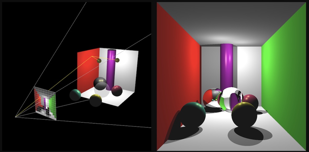
Camera
Set up the camera manually (using some trigonometry) with the following parameters:
- Position:
(0, 0, 5) - Rotation: None (i.e., Y up, -Z forward)
- Field of view: 45 degrees (see left image)
- Aspect ratio: 1.0 (i.e., square)
- Width/height of the image
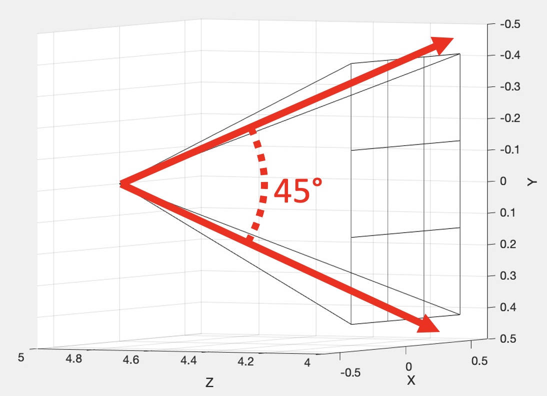
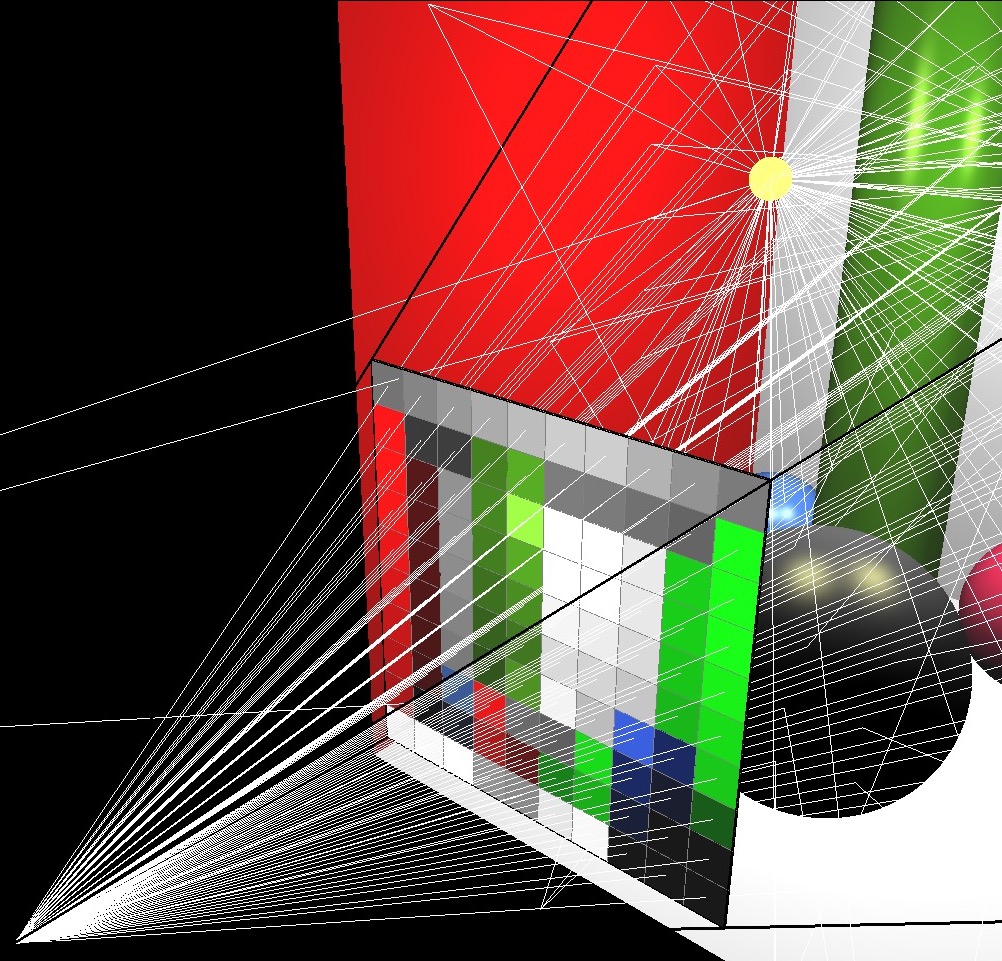
Imagine a virtual plane at Z=4.0 (i.e., one unit away from the camera, which is at Z=5.0). Our virtual rays will be starting at (0, 0, 5) and then will be going through the center of each pixel in the virtual plane. For example, in the center image, there are 9 rays, including one going straight out through the center of the middle pixel. The right image shows how these rays would look for a 10 by 10 image. (This was rendered with OpenGL for pedagogical purposes. Your code does not need to show the virtual scene in 3D.)
To start, write a function that can generate these rays given the camera specifications above, and the width/height of the output image from the commandline argument. With a 3×3 image, the 9 rays should have the following directions (each column is a unit direction vector):
    0.2572      0.0000     -0.2572      0.2662      0.0000     -0.2662      0.2572      0.0000     -0.2572
    0.2572      0.2662      0.2572      0.0000      0.0000      0.0000     -0.2572     -0.2662     -0.2572
   -0.9315     -0.9639     -0.9315     -0.9639     -1.0000     -0.9639     -0.9315     -0.9639     -0.9315
(Click here for a screenshot of the data in case your screen is too small.) Since the camera is not rotated, the middle ray’s direction is (0, 0, -1), straight ahead along the negative Z direction. Due to round-off errors, the numbers you get may be slightly different.
Scenes 1 & 2
Your first scenes consist of three spheres and one light. Scene 1 is without shadows, and Scene 2 is with shadows. If you complete Scene 2, you do not need to keep the code for Scene 1. In other words, when the <SCENE> argument is set to 1, either of the images below will give you full points. When the <SCENE> argument is set to 2, only the right image below will give you full points.
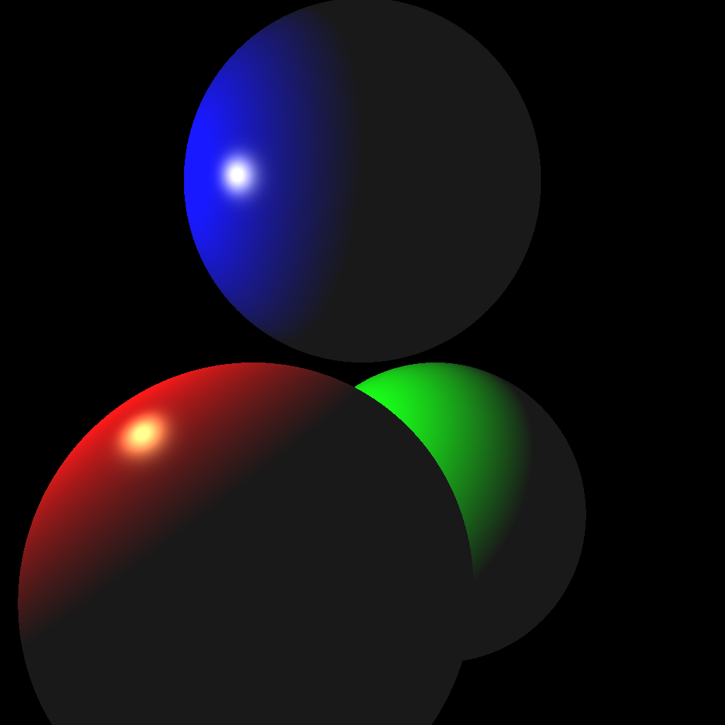
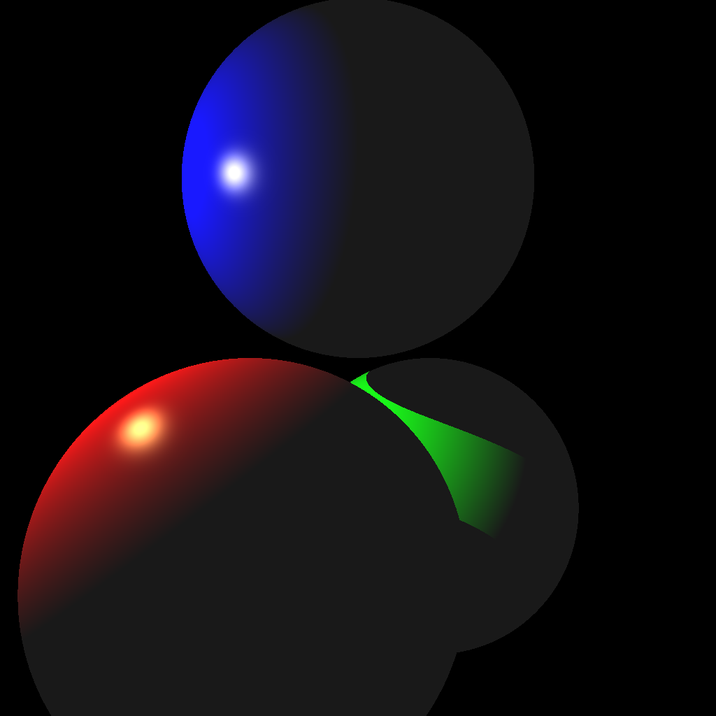
(Left) Without shadows. (Right) With shadows.
To create the scene, you can hard code the values in your code. (You may also use a parser if you prefer.) These values must be used when the command line argument <SCENE> is set to 1 or 2. Make sure to use exactly these values, since they will be used to test your code with an automatic script.
Light
- Position:
(-2.0, 1.0, 1.0) - Intensity:
1.0
Red Sphere
- Position:
(-0.5, -1.0, 1.0) - Scale:
(1.0, 1.0, 1.0) - Rotation: none
- Diffuse:
(1.0, 0.0, 0.0) - Specular:
(1.0, 1.0, 0.5) - Ambient:
(0.1, 0.1, 0.1) - Exponent:
100.0
Green Sphere
- Position:
(0.5, -1.0, -1.0) - Scale:
(1.0, 1.0, 1.0) - Rotation: none
- Diffuse:
(0.0, 1.0, 0.0) - Specular:
(1.0, 1.0, 0.5) - Ambient:
(0.1, 0.1, 0.1) - Exponent:
100.0
Blue Sphere
- Position:
(0.0, 1.0, 0.0) - Scale:
(1.0, 1.0, 1.0) - Rotation: none
- Diffuse:
(0.0, 0.0, 1.0) - Specular:
(1.0, 1.0, 0.5) - Ambient:
(0.1, 0.1, 0.1) - Exponent:
100.0
I highly recommend writing test cases for the collision functions. For example, place a unit-radius sphere at the origin and shoot a ray from (0, 0, 5) with direction (0, 0, -1). The ray should hit the sphere at (0, 0, 1) and (0, 0, -1). Try other test cases, with a different radius and/or position, as well as different rays.
Once your intersection functions have been tested, you’re ready to start implementing a ray tracer. First, shoot just the primary view rays and not the shadow rays (Scene 1, left image above). Once you get the correct result, add the shadow rays (Scene 2, right image above).
Your code should be efficient enough to generate a 1024 by 1024 image without having to wait a long time. It should only take a few seconds at most, even on an older computer. If your code is slow, make sure you are not passing big STL vectors by value and that you are running your code in release mode. Excessively slow code will be penalized.
Also, use object-oriented design to organize your code. There should be a superclass that represents all shapes. The subclasses should implement specific intersection tests. For example, a subclass that represents an infinite plane should implement Task 2 from Lab 13, and another subclass that represents a sphere should implement Task 3 from Lab 13.
Scene 3
The next scene consists of one sphere, one ellipsoid, one infinite plane, and two lights.
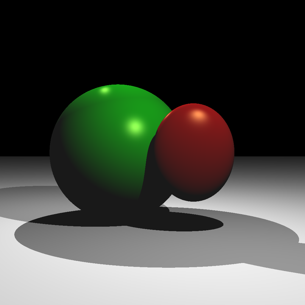
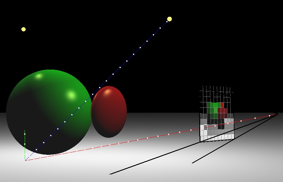
(Left) Ray traced scene. (Right) A rotated view showing one of the view rays. The blue shadow ray reaches the light, but the green shadow ray is blocked.
Light 1
- Position:
(1.0, 2.0, 2.0) - Intensity:
0.5
Light 2
- Position:
(-1.0, 2.0, -1.0) - Intensity:
0.5
Red Ellipsoid
- Position:
(0.5, 0.0, 0.5) - Scale:
(0.5, 0.6, 0.2) - Rotation: none
- Diffuse:
(1.0, 0.0, 0.0) - Specular:
(1.0, 1.0, 0.5) - Ambient:
(0.1, 0.1, 0.1) - Exponent:
100.0
Green Sphere
- Position:
(-0.5, 0.0, -0.5) - Scale:
(1.0, 1.0, 1.0) - Rotation: none
- Diffuse:
(0.0, 1.0, 0.0) - Specular:
(1.0, 1.0, 0.5) - Ambient:
(0.1, 0.1, 0.1) - Exponent:
100.0
Plane
- Position:
(0.0, -1.0, 0.0) - Rotation: Y up (normal points along +Y)
- Diffuse:
(1.0, 1.0, 1.0) - Specular:
(0.0, 0.0, 0.0) - Ambient:
(0.1, 0.1, 0.1) - Exponent:
0.0
With two lights, you should be able to see areas that are occluded from both or just one light. Also note that the ellipsoid casts a shadow on the sphere.
Scenes 4 & 5
Your next scenes consist of two lights, two Phong spheres, two reflective spheres, and two infinite planes. Scene 4 is with a single reflection, and Scene 5 is with multiple (recursive) reflections. If you complete Scene 5, you do not need to keep the code for Scene 4. In other words, when the <SCENE> argument is set to 4, either of the images below will give you full points. When the <SCENE> argument is set to 5, only the right image below will give you full points.
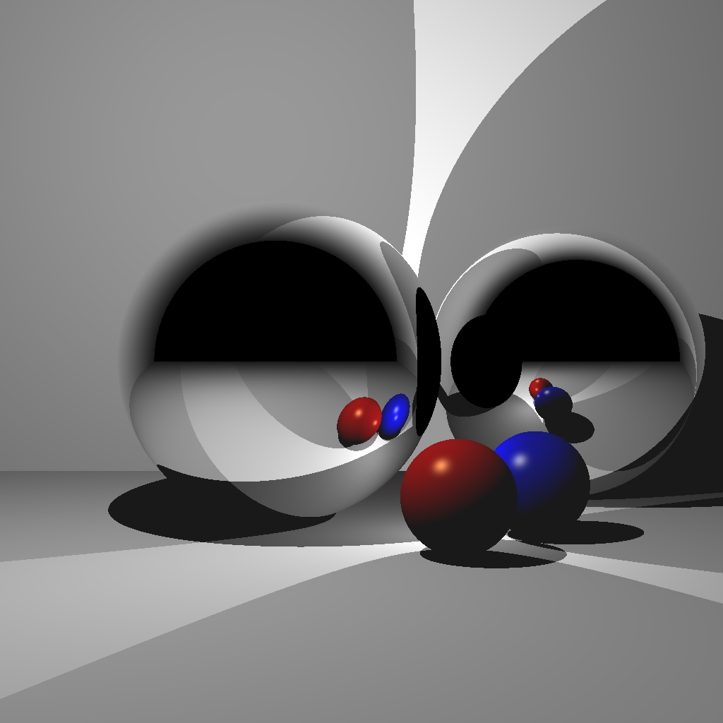
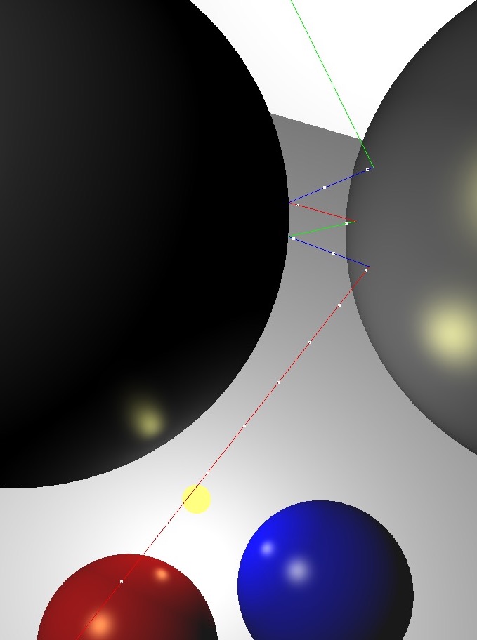
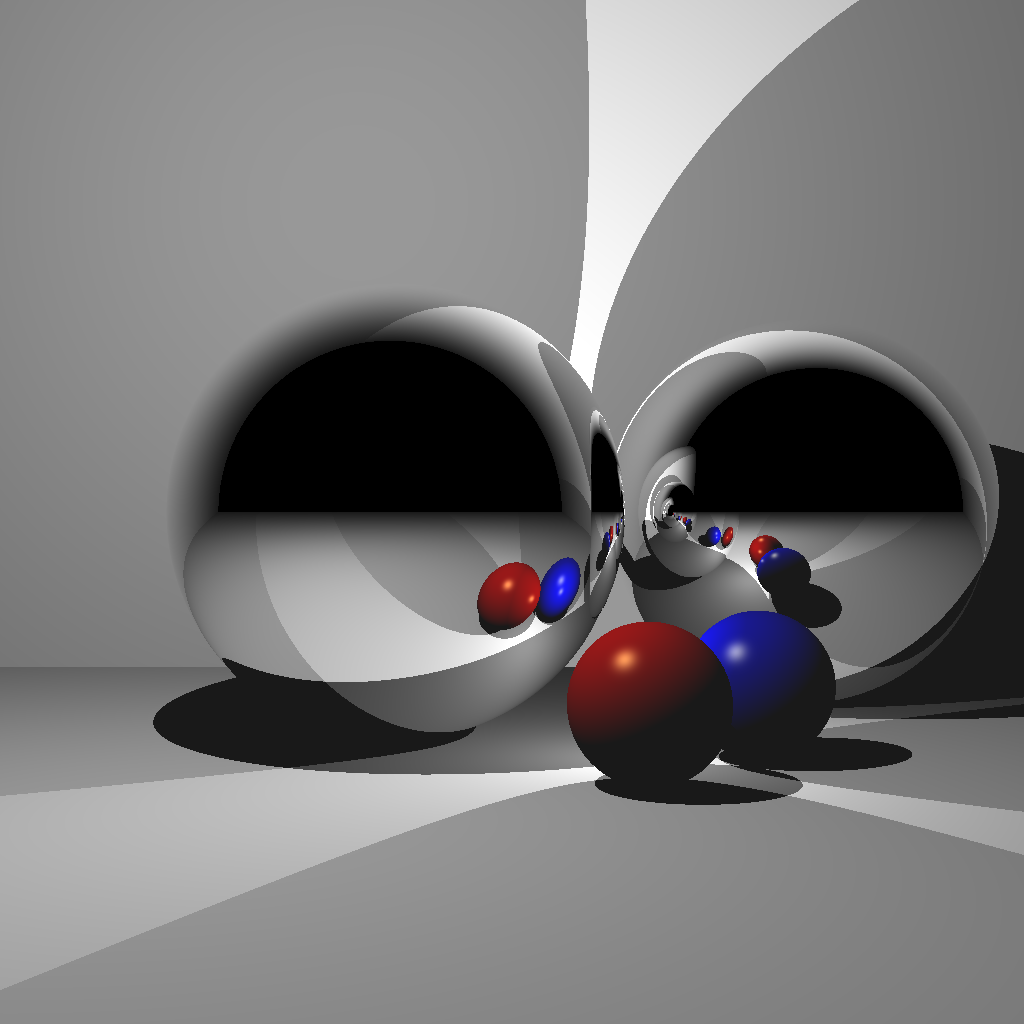
(Left) Rendered with a single bounce. Without enough recursion depth, the reflection of the other reflective sphere is not rendered. (Center) A closeup of multiple reflections. (Right) Rendered with multiple bounces.
Light 1
- Position:
(-1.0, 2.0, 1.0) - Intensity:
0.5
Light 2
- Position:
(0.5, -0.5, 0.0) - Intensity:
0.5
Red Sphere
- Position:
(0.5, -0.7, 0.5) - Scale:
(0.3, 0.3, 0.3) - Rotation: none
- Diffuse:
(1.0, 0.0, 0.0) - Specular:
(1.0, 1.0, 0.5) - Ambient:
(0.1, 0.1, 0.1) - Exponent:
100.0
Blue Sphere
- Position:
(1.0, -0.7, 0.0) - Scale:
(0.3, 0.3, 0.3) - Rotation: none
- Diffuse:
(0.0, 0.0, 1.0) - Specular:
(1.0, 1.0, 0.5) - Ambient:
(0.1, 0.1, 0.1) - Exponent:
100.0
Floor
- Position:
(0.0, -1.0, 0.0) - Rotation: Y up (normal points along +Y)
- Diffuse:
(1.0, 1.0, 1.0) - Specular:
(0.0, 0.0, 0.0) - Ambient:
(0.1, 0.1, 0.1) - Exponent:
0.0
Back Wall
- Position:
(0.0, 0.0, -3.0) - Rotation: Z up (normal points along +Z)
- Diffuse:
(1.0, 1.0, 1.0) - Specular:
(0.0, 0.0, 0.0) - Ambient:
(0.1, 0.1, 0.1) - Exponent:
0.0
Reflective Sphere 1
- Position:
(-0.5, 0.0, -0.5) - Scale:
(1.0, 1.0, 1.0) - Rotation: none
Reflective Sphere 2
- Position:
(1.5, 0.0, -1.5) - Scale:
(1.0, 1.0, 1.0) - Rotation: none
Scenes 6 & 7
For these scenes, import an obj mesh. Scene 6 is without model transformation, and Scene 7 is with model transformation. Once you finish Scene 7, you should set up your code so that Scene 6 uses the identity transform.
For triangle-ray tests, use the optimized code by Thomas Akenine-Moller. Some hints for this piece of code:
- The return value is
1or0depending on whether there was a hit. - Input arguments
origanddirare the ray origin and direction, respectively. - Input arguments
vert0,vert1, andvert2are the three vertex positions of the triangle. - Output argument
tis the distance along the ray where the hit occurred.- Make sure to check that
t > 0to deal with collisions happening behind the ray.
- Make sure to check that
- Output arguments
uandvare the barycentric coordinates of the triangle where the hit occurred.ucorresponds tovert1, andvcorresponds tovert2.
Without any optimizations, using the bunny mesh will take a very long time to render, since each ray will need to be tested against every single triangle. Add a simple optimization by putting a bounding sphere around the bunny and testing the ray against the sphere first. If the ray does not hit the sphere, you do not need to test against any of the triangles. It should not take more than a minute to render a bunny with a single light at 512×512 resolution. Make sure to run your code in release mode. We will be testing your submission with the bunny mesh.
There should be a single light in the scene, and the material should be the same as the blue sphere from the previous task.
Light
- Position:
(-1.0, 1.0, 1.0) - Intensity:
1.0
Material
- Diffuse:
(0.0, 0.0, 1.0) - Specular:
(1.0, 1.0, 0.5) - Ambient:
(0.1, 0.1, 0.1) - Exponent:
100.0
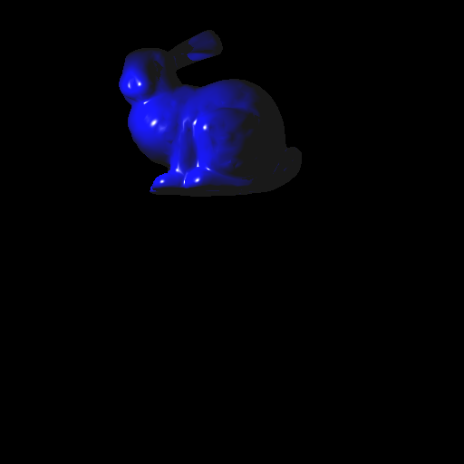
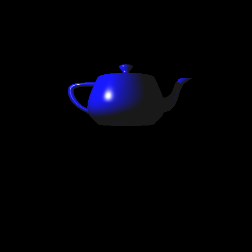
Now add the ability to transform the obj mesh. To do this, you need to transform the ray into local coordinates, perform collision detection, and then transform the result back to world coordinates. Let � be the 4×4 transformation matrix of the obj mesh. Then:
- Transform ray to local coordinates.
- Ray origin: multiply by �−1.
- Ray direction: multiply by �−1 and normalize.
- Perform collision detection in local coordinates, using the transformed ray.
- Transform results to world coordinates.
- Hit position: multiply by �.
- Hit normal: multiply by �−⊤ (inverse transpose) and normalize.
- Hit distance: compute from ray origin and hit position; �=‖�→−�→‖, where �→ is the hit position, and �→ is the ray origin, both in world coords. Remember to check if the hit point is behind the ray — see the last part of Lab 13.
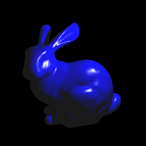
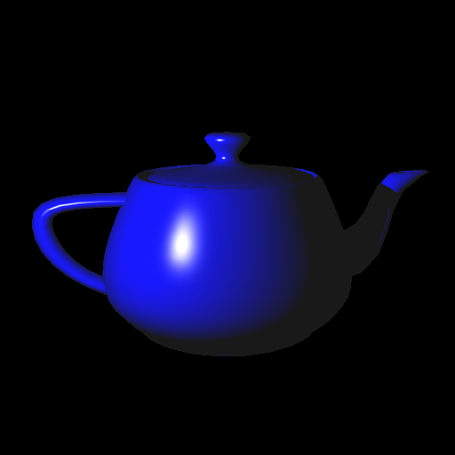
For Task 7, there should be a single light in the scene:
- Position:
(1.0, 1.0, 2.0) - Intensity:
1.0
We will be testing your submission with the bunny mesh with the following model transform:
E =

    1.5000         0         0    0.3000
         0    1.4095   -0.5130   -1.5000
         0    0.5130    1.4095         0
         0         0         0    1.0000
This transformation matrix can also be constructed as the product E = T * R * S, where
Tis a translation by(0.3, -1.5, 0.0).Ris a rotation about the X axis by 20 degrees.Sis a uniform scale by1.5.
Scene 8 (Optional for honors students)
Implement a camera that can be translated/rotated arbitrarily in the world and whose field of view can be modified. Use the same setup as Scene 1 but from a different camera location/orientation. The camera should be placed at (-3,0,0) looking along the positive X axis, with the field of view of 60 degrees. The left image is the 3D view from the original view point of Scene 1, and the right image is the resulting ray traced image.
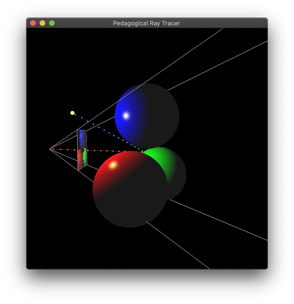
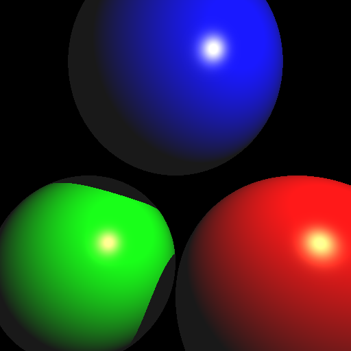
Bonus (Honors students: implement at least 10 points from here)
Once you finish the base assignment, you can earn up to 20 bonus points by implementing the following features (in no particular order):
- [+5] Multithreading – process the image pixels in parallel.
- [+5] Motion blur – have a moving object, and average the result of multiple renders.
- [+5] Blend reflection with Blinn-Phong lighting – e.g., 30% reflection and 70% Blinn-Phong.
- [+5] Find code online to accelerate the ray-triangle intersection. You can use a sphere-tree, OBB-tree, oct-tree, KD-tree, BSP-tree, etc. Remember to cite the source in the code and in the README.
- [+8] Refraction
- [+3] Infinite cylinders – you may use online code as long as you cite it in the README.
- [+3] Boxes – you may use online code as long as you cite it in the README.
- [+5] Constructive solid geometry – intersection, union, and difference.
- [+5] Perform antialiasing by generating multiple primary rays per pixel and averaging.
- [+5] Create “area” light sources that consist of multiple nearby points.
- [+5] Generate multiple reflection rays that spread out around the “exact” reflection to simulate surface roughness. The reflection calculation for the point is the average of these reflection rays.
- [+5] Include a texture-mapped object.
- [+3] Include an object or region that will attenuate light (reduce certain color of light based on distance traveled through that region -– e.g., think colored glass, or fog).
Please use Scene 0 or 9 for the bonus scenes. The other scene numbers must work as if no bonus were implemented.
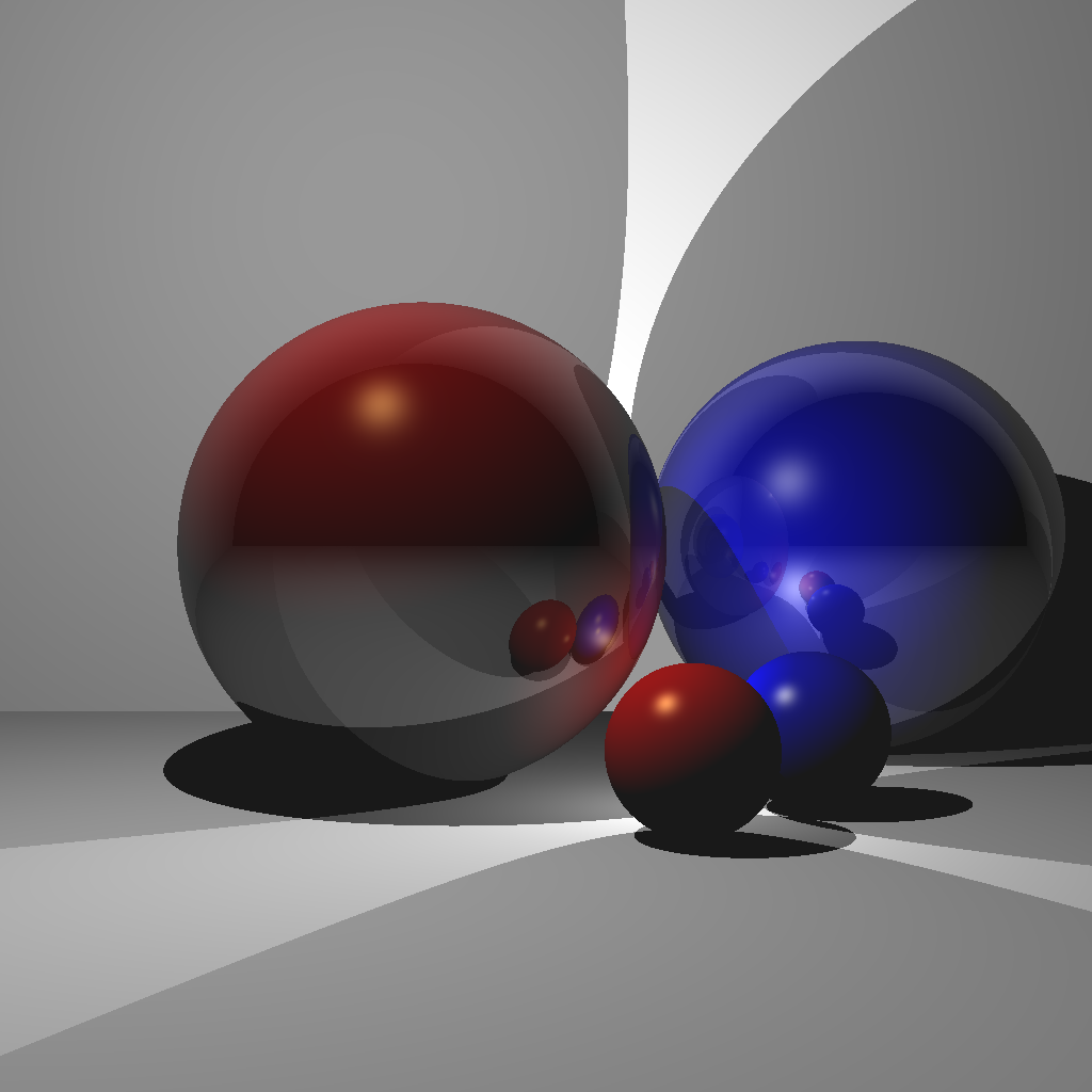
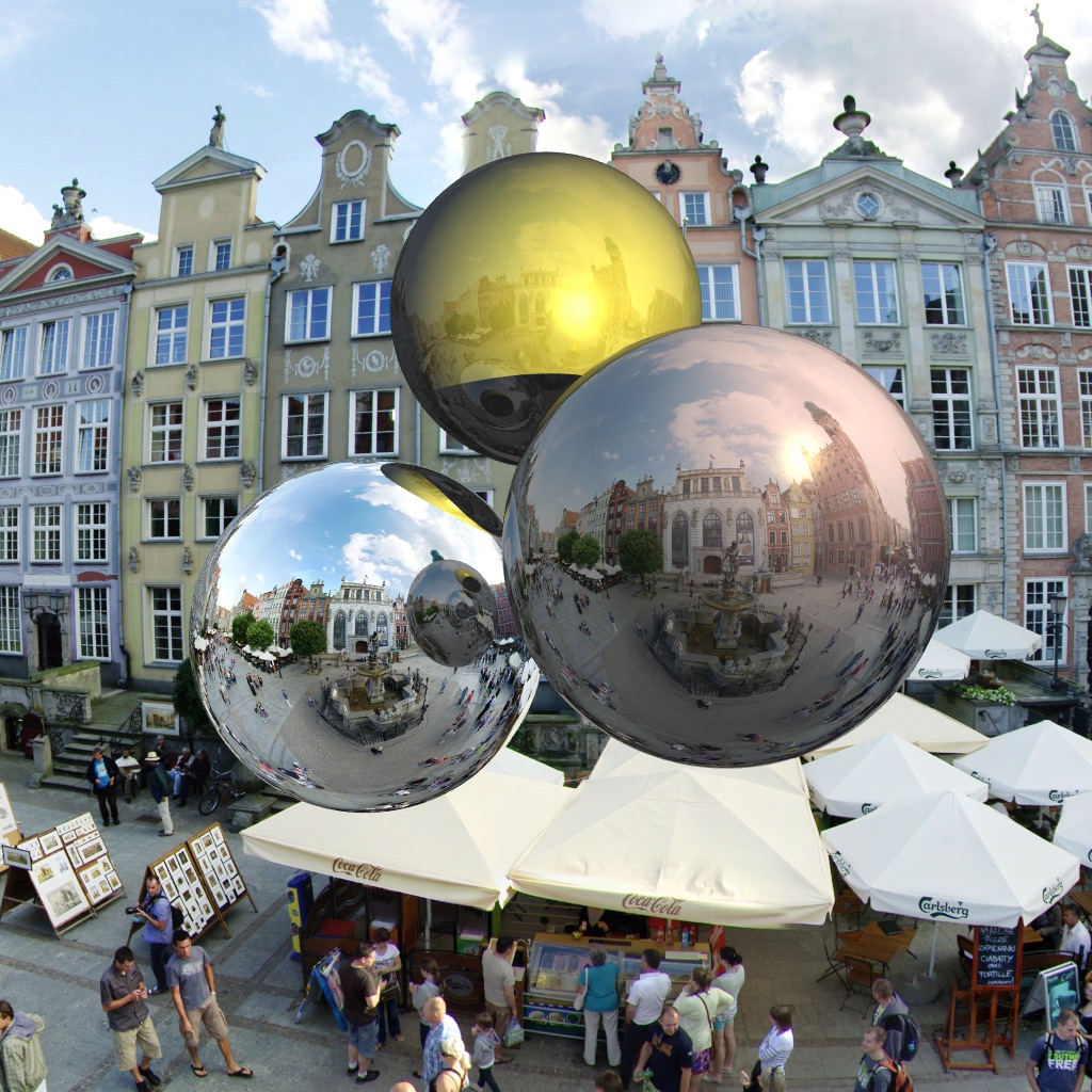
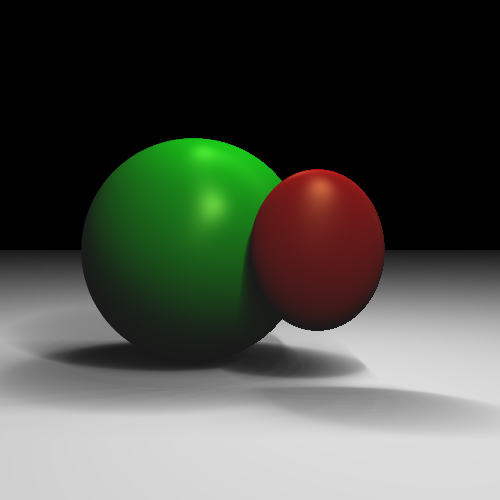
(Left) Blend between reflection and Blinn-Phong [Nkemdi Anyiam 2021]. (Center) Spherical environment mapping [Rebecca McFadden 2021]. (Right) Area lights [Michael Stewart 2021].
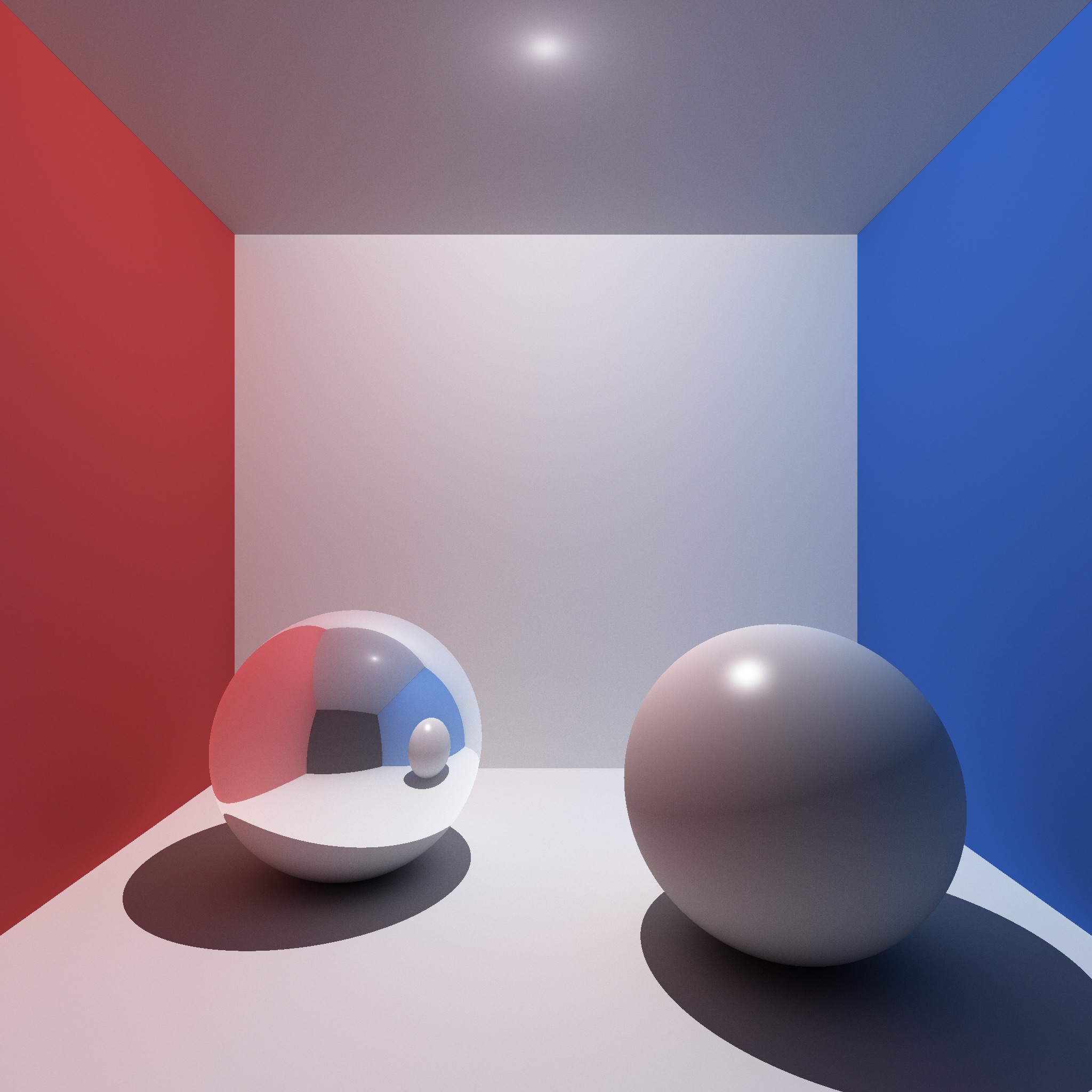
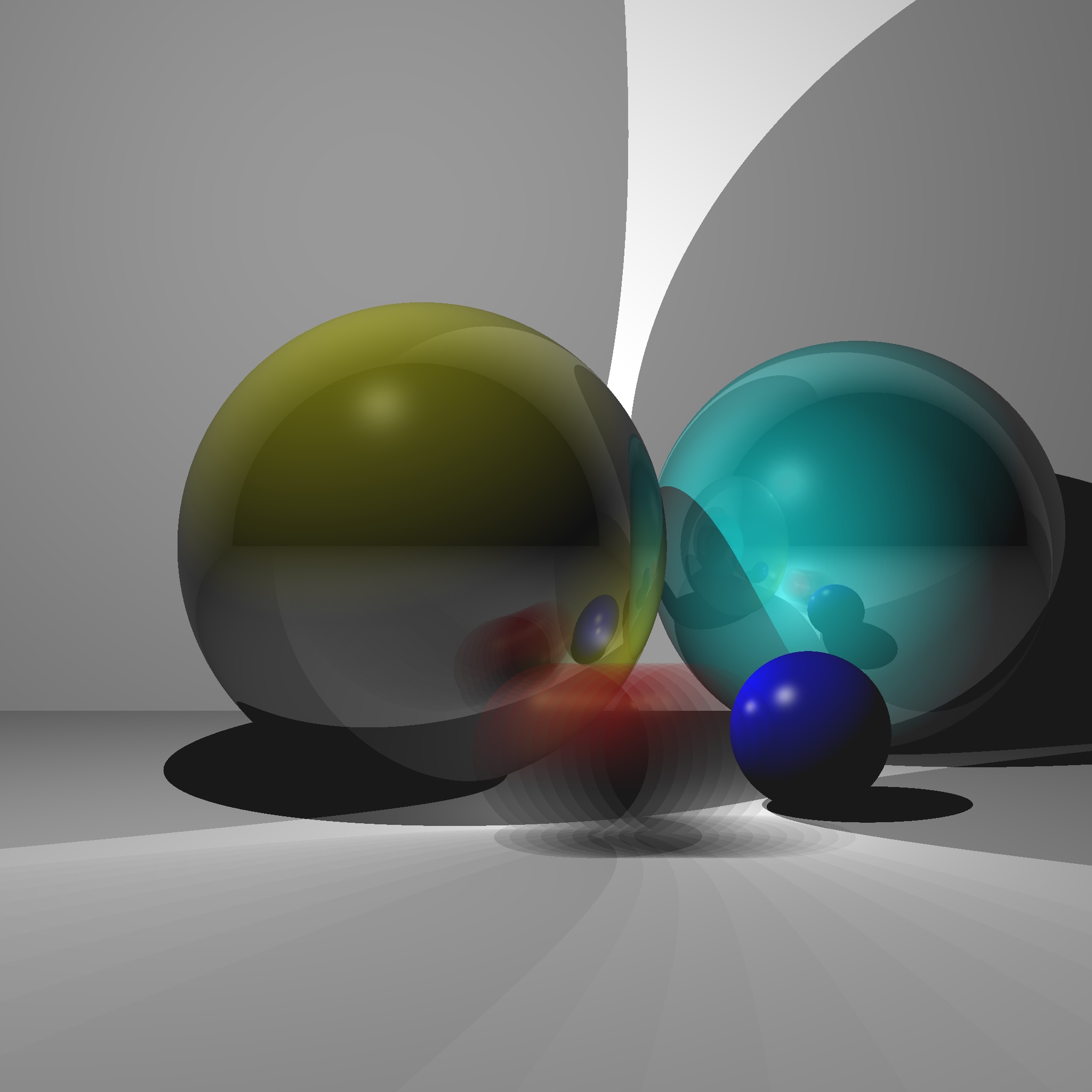
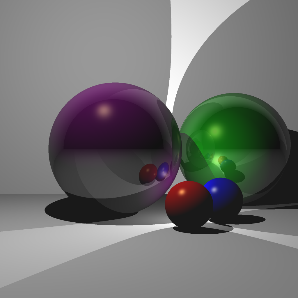
(Left) Monte-Carlo path tracing [Jonah Taylor 2021]. (Center) Reflection/Blinn-Phong and motion blur [Michael Hu 2022]. (Right) Reflection/Blinn-Phong and Anti-aliasing [Senhe Hao 2022].
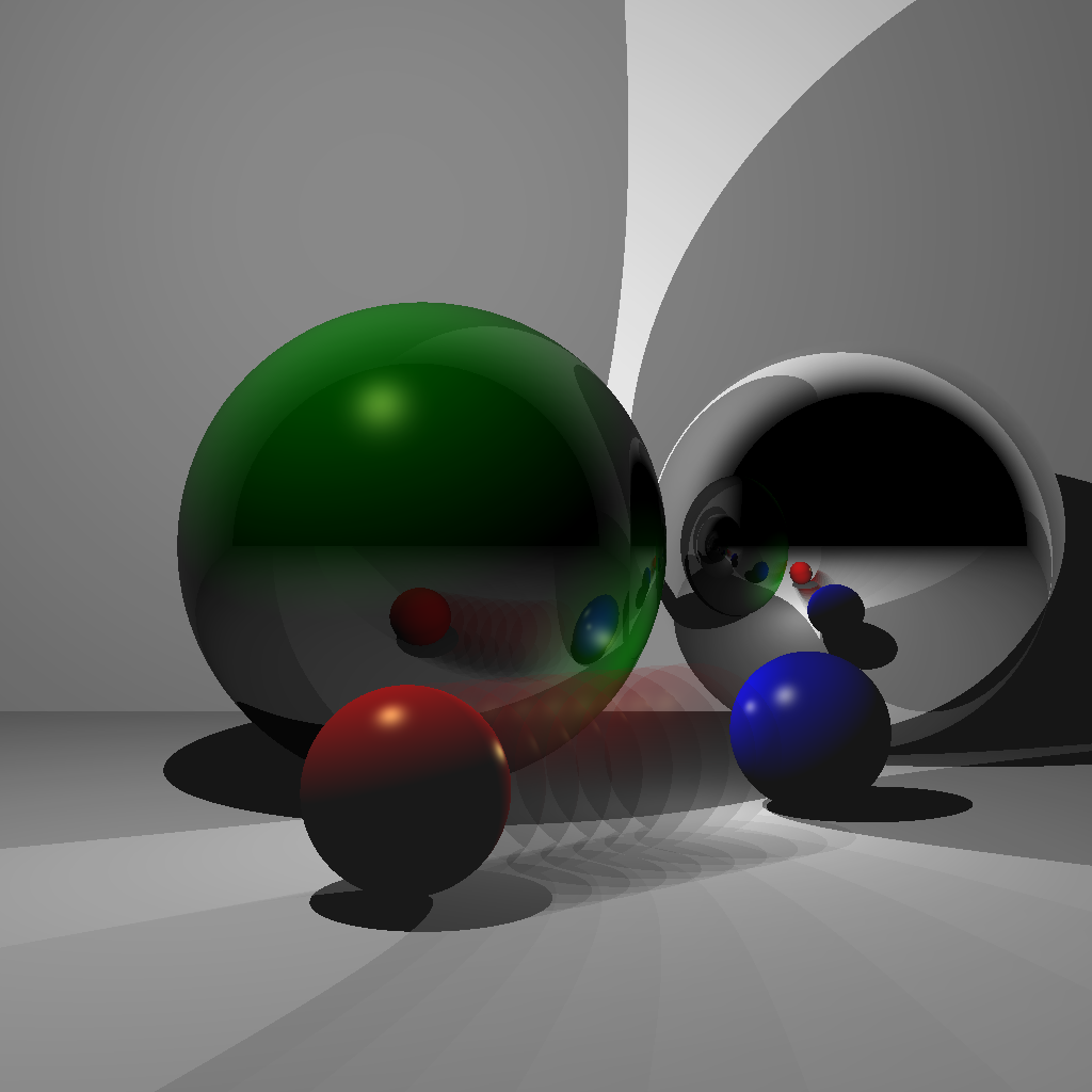
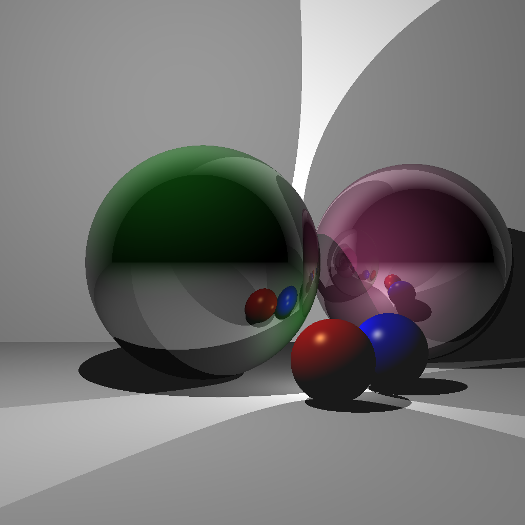
(Left/Center) Reflection/Blinn-Phong and motion blur [Samantha Hallam 2022]. (Right) Reflection/Blinn-Phong [Kunal Gupta 2022].
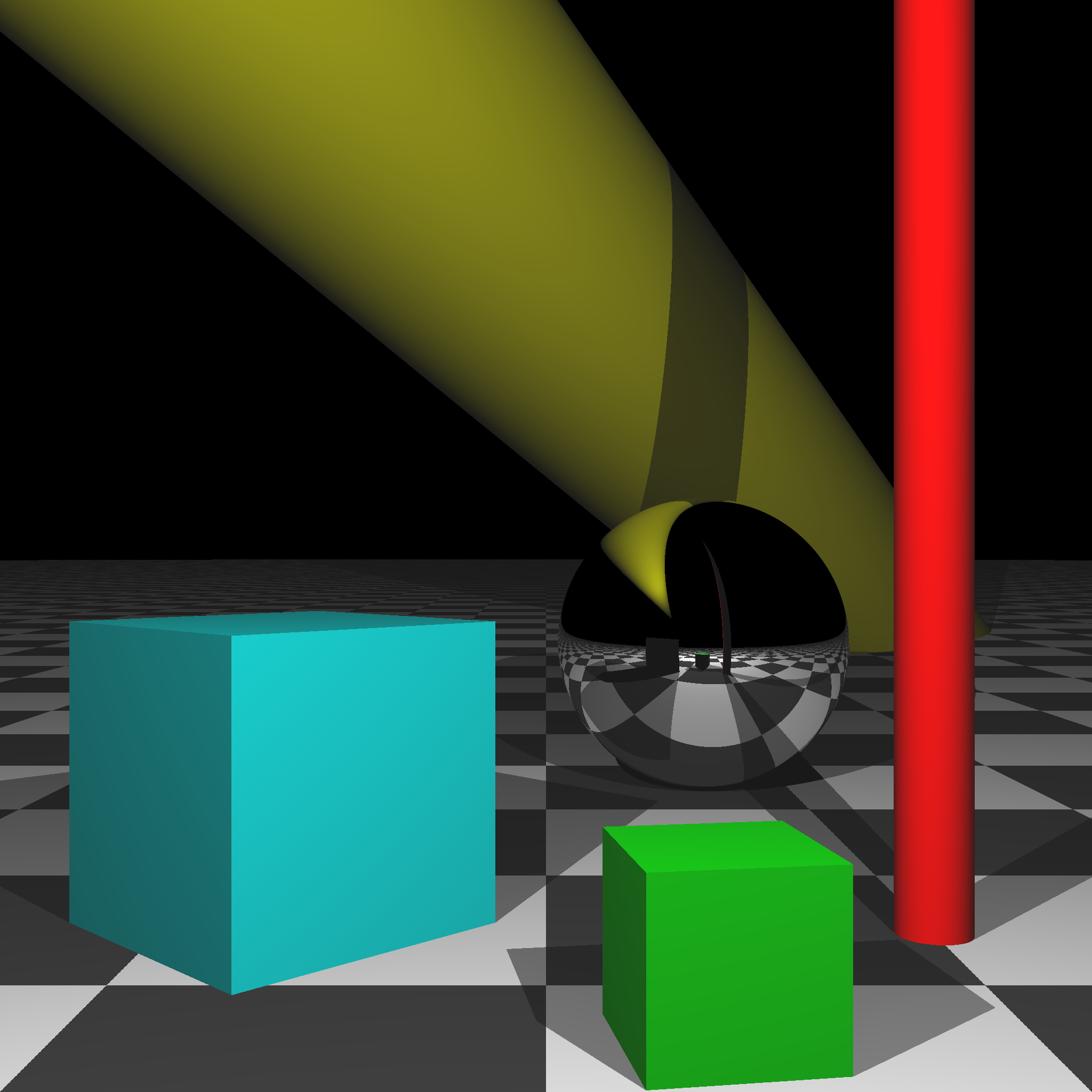
(Left) Boxes, Cylinders, and Texturing [Peter Castelein 2022]. (Right) Refraction [Raul Escobar 2022].
Grading
In each task, you must use object-oriented design to obtain full points.
- [10] Scene 1: without shadows
- [15] Scene 2: with shadows
- [15] Scene 3: with multiple lights
- [15] Scene 4: with single reflection
- [15] Scene 5: with multiple reflections
- [10] Scene 6: without transform
- [10] Scene 7: with transform
- [10] Scene 8: transformed camera
- [+20] Bonus up to 20 points
Total: 100 plus 20 bonus points.
For honors students: you must complete at least 10 bonus points. (Otherwise, you will receive a 0 on this assignment.) Like all other students, you can still finish Scene 8 and earn up to 20 bonus points to end up with 120 total points.
What to hand in
Failing to follow these points may decrease your final score. On Linux/Mac, make sure that your code compiles and runs by typing:
> mkdir build
> cd build
> cmake ..
> make
> ./A6 <SCENE> <IMAGE SIZE> <IMAGE FILENAME>
If you’re on Windows, make sure that you can build your code using the same procedure as in Lab -1.
- Make sure the arguments are exactly as specified.
- We will be running the code in release mode.
- Include an ASCII README file that includes:
- Your name, UID, and email
- The highest task you’ve completed
- Citations for any downloaded code
- Plus anything else of note
- Make sure you don’t get any compiler warnings.
- Remove unnecessary debug printouts.
- Remove unnecessary debug code that has been commented out.
- Hand in
src/,resources/,CMakeLists.txt, and your readme file. The resources folder should contain the obj files (if necessary). - Do not hand in:
- The build directory
- The executable
- Old save files
(*.~) - Object files
(*.o) - Visual Studio files
(.vs) - Git folder
(.git)
- Create a single zip file of all the required files.
- The filename of this zip file should be
UIN.zip(e.g.,12345678.zip). - The zip file should extract a single top-level folder named
UIN/(e.g.12345678/). - This top-level folder should contain your README,
src/,CMakeLists.txt, etc. - Use the standard
.zipformat (not.gz,.7z,.rar, etc.).
- The filename of this zip file should be